|
<< Click to Display Table of Contents >> Connection and Pinout |
  
|
|
<< Click to Display Table of Contents >> Connection and Pinout |
|
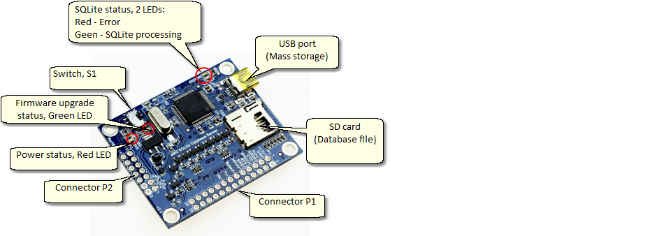
No use.
This LED indicate the process of Firmware upgrade.
1. LED turn ON when Firmware upgrade process is busy, turn on time should less than 20 seconds. And turn off when normal operation.
2. LED blinking 5Hz when upgrade process is not completed (did not indicate success or fail).
Led turn on when apply 3.3V or USB power to the board.
1. Red LED, indicate failure on SQLite query/statement.
2. Green LED, indicate busy status.
Interface pins connector 1
Pin |
Function |
Description |
1 |
- |
+ 3.3V |
2 |
- |
GND |
3 |
- |
Reserved |
4 |
- |
Reserved |
5 |
- |
Reserved |
6 |
- |
Reserved |
7 |
- |
Reserved |
8 |
- |
nRESET |
9 |
- |
Reserved |
10 |
- |
Reserved |
11 |
Input |
UART-Speed. Pull-up this pin to High to configure UART speed to 1000000 (default), set this pin to Low to configure UART speed to 115200. |
12 |
- |
Reserved |
13 |
Output |
UART-Tx |
14 |
Input |
UART-Rx |
15 |
- |
Reserved |
16 |
- |
Reserved |
17 |
- |
Reserved |
18 |
- |
Reserved |
19 |
- |
Reserved |
20 |
- |
Reserved |
21 |
- |
Reserved |
22 |
- |
Reserved |
23 |
- |
Reserved |
24 |
- |
Reserved |
25 |
- |
Reserved |
26 |
- |
Reserved |
Interface pins connector 2
Pin |
Function |
Description |
1 |
- |
Vin +5V (Optional) |
2 |
- |
GND |
3 |
- |
+ 3.3V |
4 |
- |
GND |
5 |
- |
Reserved |
6 |
- |
Reserved |
7 |
- |
nRESET |
8 |
Input |
UART-Rx |
9 |
Output |
UART-Tx |
10 |
Input |
UART-Speed. Pull-up this pin to High to configure UART speed to 1000000 (default), set this pin to Low to configure UART speed to 115200. |
11 |
- |
Reserved |
12 |
- |
Reserved |
13 |
- |
Reserved |
14 |
- |
Reserved |