|
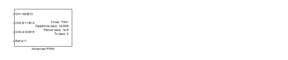
<< Click to Display Table of Contents >> Advanced PWM Block |
  
|
|
<< Click to Display Table of Contents >> Advanced PWM Block |
|
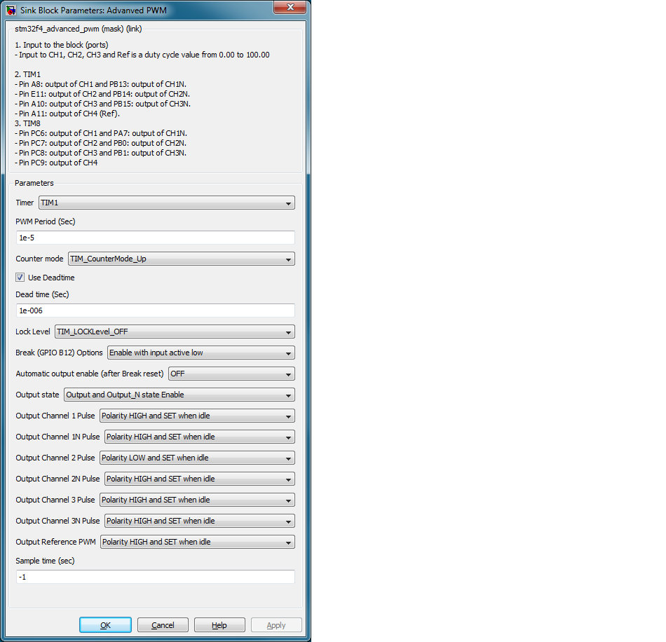
Configuration item |
Selectable option/ Value |
Description |
Timer |
TIM1/ TIM8 |
Select timer source for PWM signal generation |
PWM period (Sec) |
Variable from 0 to 100 |
Set the period of signal. Period is a constant value and cannot changed when running. |
Counter mode |
TIM_CounterMode_Up TIM_CounterMode_Down TIM_CounterMode_CenterAligned1 TIM_CounterMode_CenterAligned2 TIM_CounterMode_CenterAligned3 |
Select counter Up/ Down or Center-Aligned mode. |
Use Deadtime |
Checked/ Unchecked |
Enable/ Disable Deadtime configuration. |
Dead time (Sec) |
constant value 0 to 6uS |
Configure the Deadtime value. |
Lock Level |
TIM_LOCKLevel_OFF TIM_LOCKLevel_1 TIM_LOCKLevel_2 TIM_LOCKLevel_3 |
Configuration the LOCK to prevent register setup changed by un-expect write bit (software error) during runtime. |
Break Options |
Disable Enable with input active high Enable with input active low |
Break option. For Timer1, break input signal pin is PB12. For Timer8, break input signal pin is PA6. |
Automatic output enable |
ON/ OFF |
ON: Output auto enable after break input is reset. OFF: Output latched shutdown when break. |
Output state |
Output state Enable Output_N state Enable Output and Output_N state Enable |
Output state Enable: CH1, CH2, CH3, CH4(Ref) can be configured to enable. Output_N state Enable: CH1N, CH2N, CH3N can be configured to enable. Output and Output_N state Enable: All PWM output can be configured to enable. |
Output Channel x/xN Pulse (x=1,2,3 and 4) |
Automatic Polarity HIGH and SET when idle Polarity HIGH and RESET when idle Polarity LOW and SET when idle Polarity LOW and RESET when idle |
Configured the output channel polarity and idle state. If both CHx and CHxN are configured as Automatic, then PWM output CHx will be disabled. |
Sample time (Sec) |
(Sample time in unit of seconds) |
Time interval to update duty cycle. |
This block implement PWM generation upto 7 output with variable of duty cycle, complementary outputs and dead-time which required in power electronics control, motor control and other advance control application.
When drop this block into a model, it will enable feature of "Advanced-control timers (TIM1&TIM8)" and apply setting as user configuration.