|
<< Click to Display Table of Contents >> CAN Transmit-Receive |
  
|
|
<< Click to Display Table of Contents >> CAN Transmit-Receive |
|
Demo File: stm32f4_can_demo.mdl
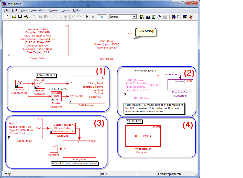
CAN transmit data packet with following ID:.
- ID 0 at time step: 0, 2, 4, 8, ...
- ID 1 at time step: 1, 3, 5, 7, ...
Transmit value is counting number from 0 to 15.
CAN Receive block, filter with ID Mask 0x07FE. For Standard ID (11 bits), 0x7FE mean bit '0' don't care and other bits must match to ID pattern. This CAN Receive block will filter only ID 0 and 1.
Output of block is function-call, it generates event call when receive Standard ID 0 or 1. In function-call subsystem, use CAN Message block to get input packet from CAN message buffer.
CAN Transmit packet with ID 2. It sent packet only when Button (pin A0) pressed.
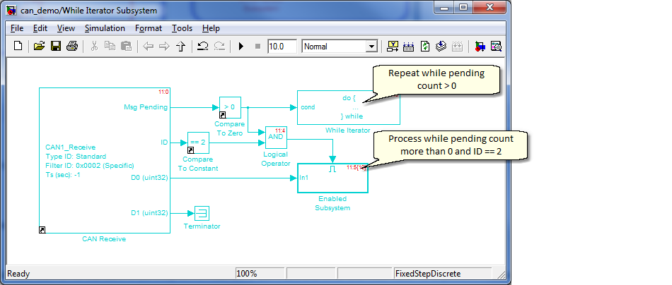
CAN Receive block using non-ISR output. The block will return number of pending message in buffer. Use While Iterator Subsystem to process all pending message.
Select CAN Tx/Rx pin from CAN Setup block. This demo using pin B9 for CAN_Tx and B8 for CAN_Rx.
This demo require two STM32F4DISCOVERY boards for testing. Build and download same model to board #1 and #2.
If CAN communication working properly, LED Yellow and LED Orange will blink with 320ms period (ON 160ms, OFF 160ms).
If button pressed, LED Red on other board will toggling.