|
<< Click to Display Table of Contents >> Design specification |
  
|
|
<< Click to Display Table of Contents >> Design specification |
|
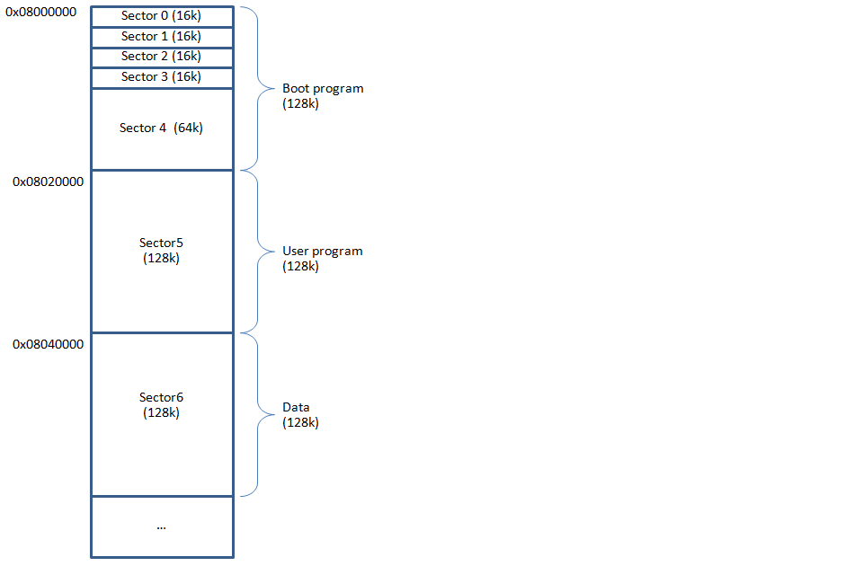
This sector is program compile with default configuration, flash base address start at 0x08000000.
Flow chart:
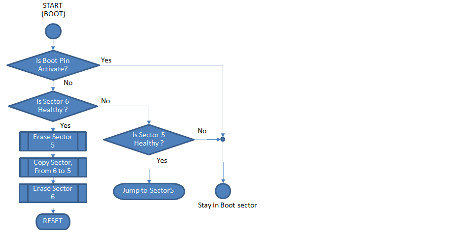
The implementation of the above bootloader program / mechanism is provided in a form of Simulink Boot Loader demo model.
In boot program must implement method to detect the corrupt firmware.
This sector compiled with Flash base offset configuration.
This is Data sector, MCU did not run in this sector. It used for storing the receiving program data for temporary.
The demo use CAN for programming interface, below specification for CAN packet.
1. Device ID
1.1 Use Standard ID (11 bits) for CAN-IAP demo.
1.2 Bit 10 of ID is reserved and must be ‘1’ to specify ID is for IAP command.
1.3 Bits 9:8 of ID used for identify IAP type.
Type 0: CAN-IAP packet is COMMAND.
Type 1: CAN-IAP packet is STATUS
Type 2: CAN-IAP packet is DATA.
Type 3: Reserved
1.4 Bits [7:0] of ID use for device ID
3.1 COMMAND packet (Bits 9:8 = 0)
3.1.1 This packet type normally sent by Host.
3.1.2 Packet data will be D0: uint32, D1: uint32.
3.1.3 D0 is IAP_CMD.
3.1.4 D1 is constant value 0x00000000.
3.2 STATUS packet (Bits 9:8 = 1)
3.2.1 This packet type normally sent by Device.
3.2.2 Packet data will be D0: uint32, D1: uint32.
3.2.3 D0 is IAP_STA.
3.2.4 D1 is constant value 0x00000000.
3.3 DATA packet (Bits 9:8 = 2)
3.3.1 This packet type normally sent by Host.
3.3.2 Packet data will be D0: uint32, D1: uint32.
3.3.3 D0 is IAP_OFFSET.
3.3.4 D1 is IAP_DATA.
3.4 RESERVED (Bits 9:8 = 3)
4.1 Command 0: IAP initial state.
4.2 Command 1: IAP Finalize state.
4.3 Command 2: MCU reset.
4.4 Command 3-7: Reserved.
Status 0: Success. Otherwise: Fail.
This will be flash memory offset, start from 0.
This is Word data (32 bits) to program into flash.