|
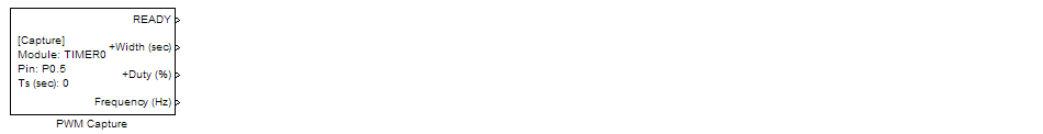
<< Click to Display Table of Contents >> PWM Capture |
  
|
|
<< Click to Display Table of Contents >> PWM Capture |
|
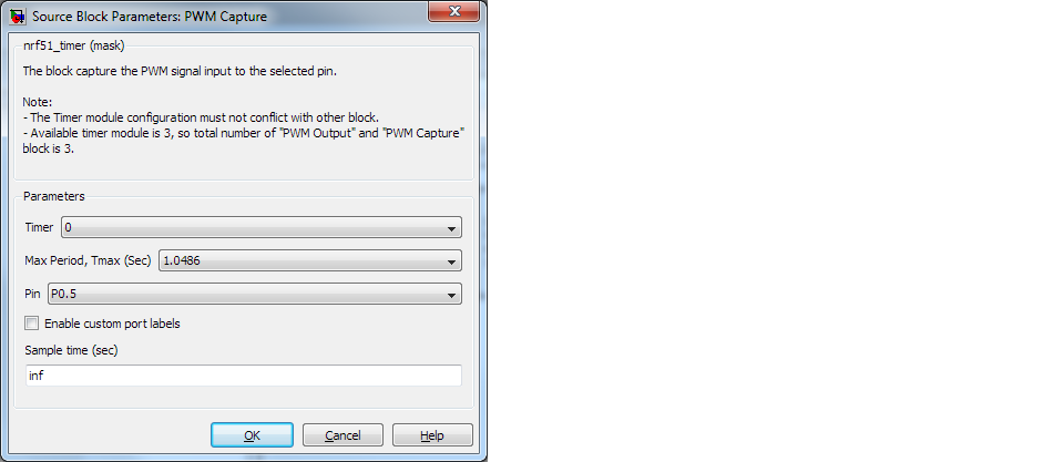
Configuration item |
Selectable option/ Value |
Description |
|---|---|---|
Timer |
0 | 1 | 2 |
|
Max Period, Tmax (Sec) |
0.004096 | 0.008192 | 0.016384 | 0.032768 | 0.065536 | 0.13107 | 0.26214 | 0.52429 | 1.0486 | 2.0972 |
Select maximum period of signal to capture. The block will return 0% duty for signal Low longer than this max period, and 100% for signal High longer than this max period. |
Pin |
(Select pin to capture PWM input signal) |
|
Sample time (sec) |
(Specify block sample time) |