|
<< Click to Display Table of Contents >> Digital Output |
  
|
|
<< Click to Display Table of Contents >> Digital Output |
|
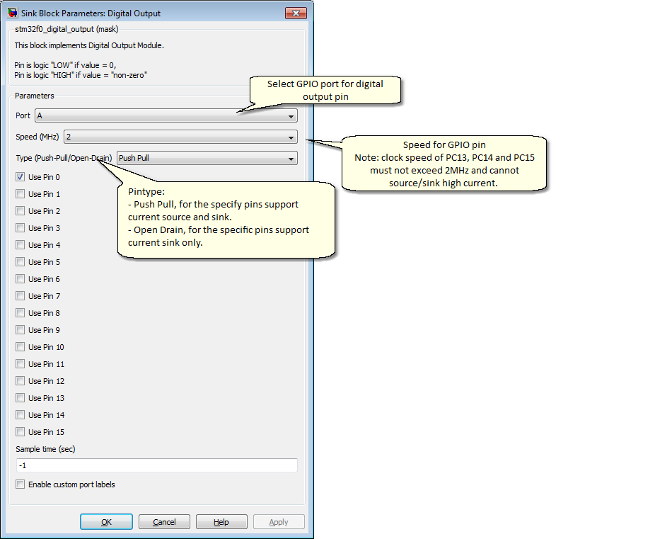
Configuration item |
Selectable option/ Value |
Description |
Port |
A | B | C | D | E | F |
Select GPIO port for specify pins |
Speed (MHz) |
2 | 10 | 50 |
Select GPIO clock speed for specify pins |
Type (Push-Pull/Open-Drain) |
Push Pull | Open Drain |
Pin type for specify pins |
Use pin 0, ..., 15 |
Checked | Unchecked |
Select pin number for specify GPIO port. |
Sample Time (Sec) |
(sampletime) |
Specify block sample time. |
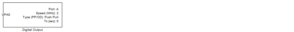
This block implements Digital Output Module to generate digital output logic from MCU pin.
Input port accepts any native kind of Simulink data type.
MCU will generate output from logic pins based on the following logic.
if (input port == 0)
Output pin Logic "Low"
else
Output pin Logic "High"
end
Available ports and pins shown depend on selected MCU (in the Target Setup Block).