|
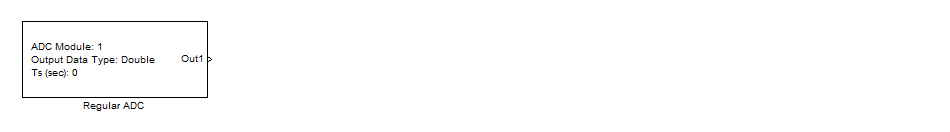
<< Click to Display Table of Contents >> Regular ADC |
  
|
|
<< Click to Display Table of Contents >> Regular ADC |
|
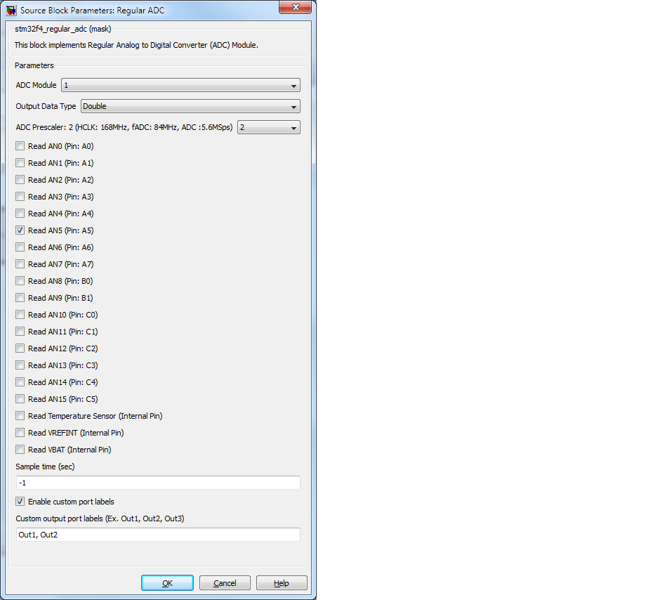
Configuration item |
Selectable option/ Value |
Description |
ADC Module |
1 2 3 |
There are 3 modules available. |
Output Data Type |
Double Single Raw (uint16) |
Select output data type for each ADC output port. |
ADC Prescaler |
Auto 2 4 6 8 |
Select ADC clock prescaler to optimize the conversion speed. |
Read ANx; x=0 to 15 |
Checked/ Un-checked |
Check: Enable ADC channel Un-checked: Disable ADC channel. |
Read Temperature Sensor |
Checked/ Un-checked |
Check: Enable reading internal temperature sensor. Un-checked: Disable. |
Read VREFINT |
Checked/ Un-checked |
Check: Enable reading internal voltage reference. Un-checked: Disable. |
Read VBAT |
Checked/ Un-checked |
Check: Enable reading VBAT level. Un-checked: Disable. |
Sample Time (Sec) |
Sample time value in unit of second, default -1. |
Configuration block sample time value. |
Enable custom port labels |
Checked/ Un-checked |
Checked: enable custom port labels. |
Custom output port labels |
Port label with comma separate value. |
Put the desired string to appear on port labels. |
Use this block for the application which need to process analog signal by software. Example, reading level of analog sensor (Temperature, Pressure, etc.), measure voltage and current from sensing circuit.
The Block's output are digital values between 0 to 4095. (STM32F4 ADC is 12 bits resolution.)
This block will setup ADC reading function and return the reading value in every time step.