|
<< Click to Display Table of Contents >> Regular DAC |
  
|
|
<< Click to Display Table of Contents >> Regular DAC |
|
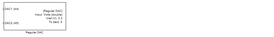
Use the Digital to Analog Convertor (DAC) Block to generate analog signals. For all STM32F4xx, a maximum of 2 analog channels can be generated simultaneously.
| 1. | Channel 1 = Pin A4 |
| 2. | Channel 2 = Pin A5 |
The DAC module of STM32F4xx has the following specifications.
| 2 x 12-bits 1MHz Sample per second DAC converters: one for each output channel |
| Better resolution can be controlled with input voltage reference VREF |
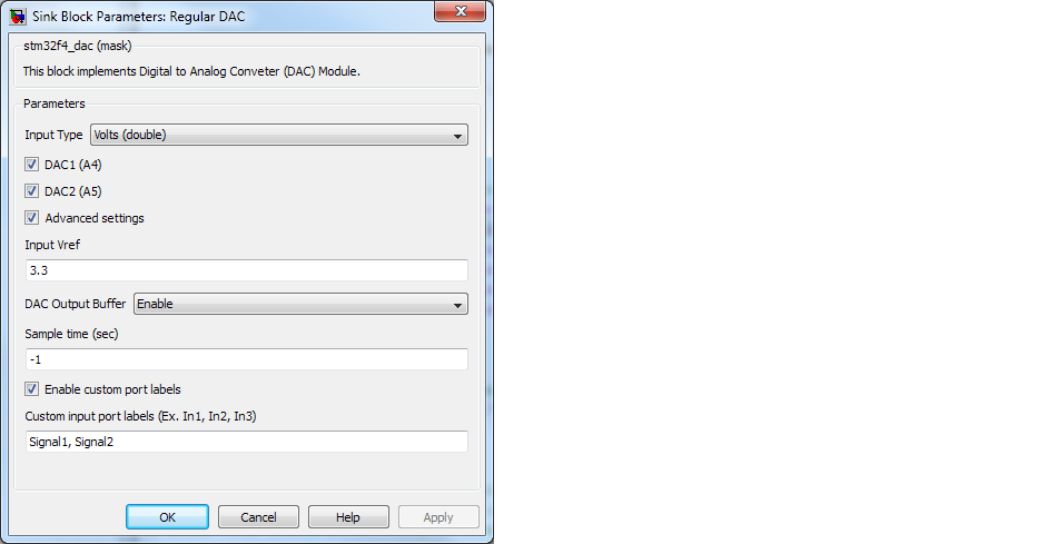
The DAC block takes inputs as either voltage (between - 3.3V) or raw data (between 0 - 4095) and generated output analog signals according to the following equation.
Analog output voltage = VREF x DOR / 4095
where DOR is the required DAC register value.
For voltage input, DOR is computer as follow:
DOR = (INPUT_VOLTS x 4095) / VREF
For raw data (both 8 and 12 bits) input, DOR is computer as follow:
DOR = INPUT_RAW
The DAC Module is based on software simultaneous trigger configuration.