|
<< Click to Display Table of Contents >> Basic PWM |
  
|
|
<< Click to Display Table of Contents >> Basic PWM |
|
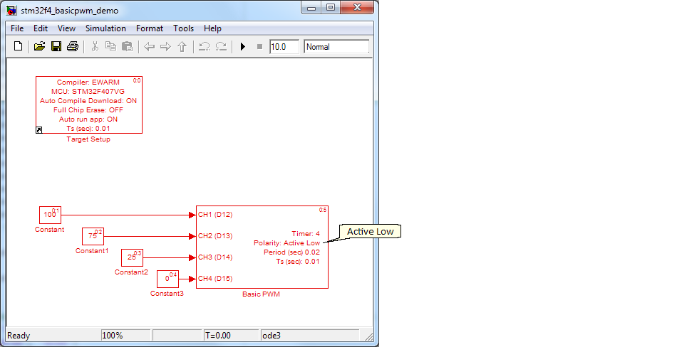
Demo File: stm32f4_basicpwm_demo.mdl
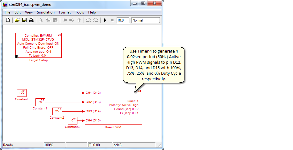
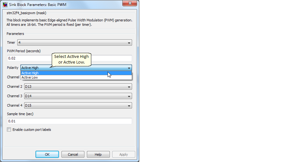
This example demonstrates how to use the Basic PWM Block to configure Timer 4 generate Active High PWM signals with 0.02 seconds period.
4 PWM signals are generated as follows.
| Channel 1 = D12 (100% Duty Cycle) |
| Channel 2 = D13 (75% Duty Cycle) |
| Channel 3 = D14 (25% Duty Cycle) |
| Channel 4 = D15 (0% Duty Cycle) |
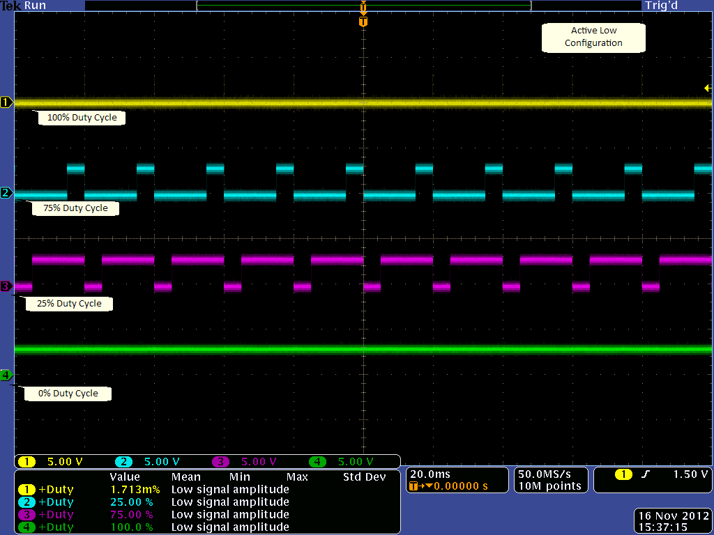
4 PWM Signals should be generated as shown below.