|
<< Click to Display Table of Contents >> CAN to Serial bridge (binary mode) |
  
|
|
<< Click to Display Table of Contents >> CAN to Serial bridge (binary mode) |
|
Demo File: stm32f0_can_slave_demo.mdl
Location: waijung_<version>\targets\stm32f0_target\stm32f0\demo\can_serial_bridge_demo\
This model file will be Build and Run on the STM32F0 Target, it works as CAN slave (device Node 1: ID=128) for test the "CAN-UART bridge" module.
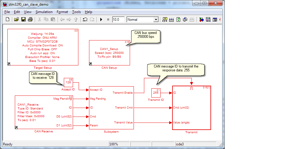
CAN message receiving is 8 bytes data, separated into 2 uint32. First is command (Cmd) and second is parameter (Param).
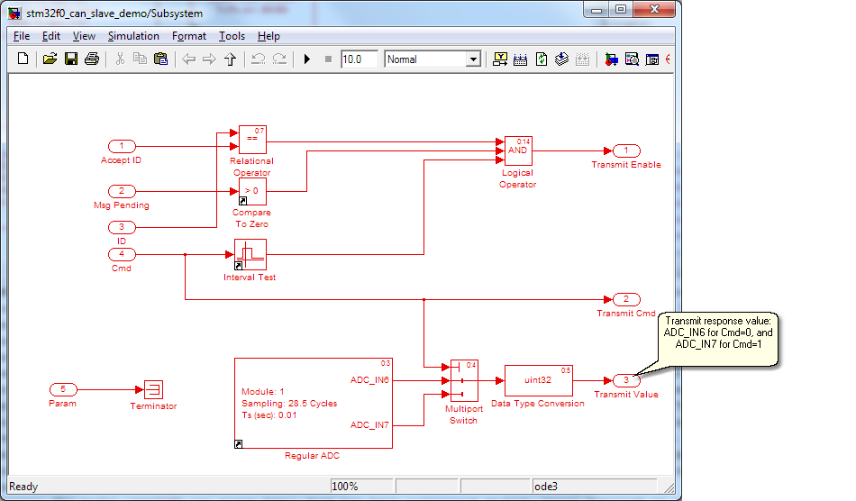
CAN slave device return ADC measurement value from ADC_IN6 for Cmd=0, ADC_IN7 for Cmd=1.
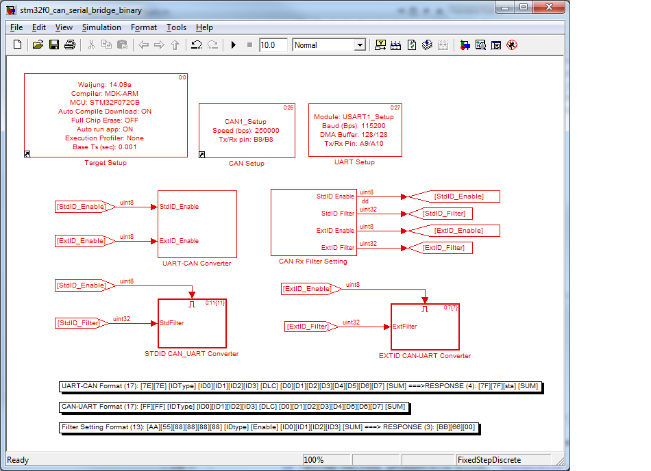
Demo File: stm32f0_can_serial_bridge_binary.mdl
Location: waijung_<version>\targets\stm32f0_target\stm32f0\demo\can_serial_bridge_demo\
This model file will be Build and Run to the STM32F0 Target, for working as CAN to UART bridge. In forward data transmission, it poll for receiving data packet from Host PC then translate and re-direct to CAN bus. In reverse data transmission, it poll for data from CAN bus message which ID matched to the ID filter setting, then transmit to Host PC via UART.
The demo showing how to communicate to CAN node via serial (UART), this demo model work as CAN-Serial bridge (also Serial-CAN). Example usage is Hardware in the loop simulation via CAN bus, showing as below picture.
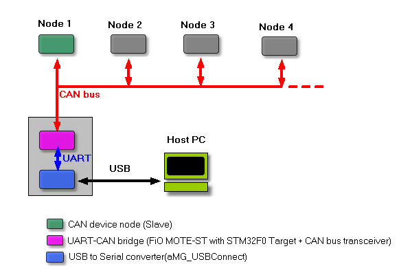
CAN to Serial bridge
Module aMG_USBConnect used for communication with Host PC for command and data, it also used as programmer tool during Waijung auto compile and download.
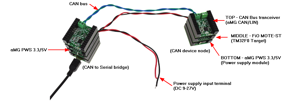
Setup for communicate to a device node.
This section describe the protocol implemented in demo model: "stm32f0_can_serial_bridge_binary.mdl".
Host PC send command packet to "CAN to Serial bridge" module for ID type and filter configuration to receive. The module will monitor CAN Bus and response only if CAN message ID and ID type matched to filter setting. In case of Host PC require to receive all ID on the bus, use ID 0xFFFFFFFF (ID0=FF, ID1=FF, ID2=FF and ID3=FF) for filter setting. Following command is packet format for filter setting.
Format (hex): [AA][55][88][88][88][88][IDType][Enable][ID0][ID1][ID2][ID3][SUM]
Where,
[AA] [55][88][88][88][88] - Transmit packet header for filter setting command
[IDType] - 0 for Extended ID and 1 for Standard ID.
[Enable] - 1 to Enable CAN receive for the specified ID type and filter, 0 to disable.
[ID0] - ID byte 0, ID[7:0]
[ID1] - ID byte 1, ID[15:8]
[ID2] - ID byte 2, ID[23:16]
[ID3] - ID byte 1, ID[31:24]
[SUM] - Sum of transmitting bytes = uint8(AA + 55 + 88 + 88 + 88 + 88 + IDType + Enable + ID0 + ... +ID3)
The "CAN to Serial bridge" module will response following packet indicates the setting is valid.
Format (hex): [BB][66][00]
Host PC start transmit data to CAN by send following command to "CAN to Serial bridge" module:
Format (hex): [7E][7E][IDType][ID0][ID1][ID2][ID3][DLC][D0][D1][D2][D3][D4][D5][D6][D7][SUM]
Where,
[7E] [7E] - Transmit packet header
[IDType] - 0 for Extended ID and 1 for Standard ID.
[ID0] - ID byte 0, ID[7:0]
[ID1] - ID byte 1, ID[15:8]
[ID2] - ID byte 2, ID[23:16]
[ID3] - ID byte 1, ID[31:24]
[DLC] - Data length code 1-8
[D0] ... [D7] - CAN data
[SUM] - Sum of transmitting bytes = uint8(7E + 7E + IDType + ID0 + ... + D7)
Then the "CAN to Serial bridge" module will response the status of CAN data operation as following format:
Response (hex): [7F][7F][sta][SUM]
[7F] [7F] - Response packet header
[sta] - CAN transmit status, a zero indicates Success.
[SUM] - Sum of response bytes = uint8(7F + 7F + sta)
When CAN data on the bus match to the filter setting, module CAN to Serial bridge will response following packet to Host PC:
Format (hex): [FF][FF][IDType][ID0][ID1][ID2][ID3][DLC][D0][D1][D2][D3][D4][D5][D6][D7][SUM]
Where,
[FF][FF] - Binary packet header
[IDType] - 0 for Extended ID and 1 for Standard ID.
[ID0] - ID byte 0, ID[7:0]
[ID1] - ID byte 1, ID[15:8]
[ID2] - ID byte 2, ID[23:16]
[ID3] - ID byte 1, ID[31:24]
[DLC] - Data length code 1-8
[D0] ... [D7] - CAN data
[SUM] - Sum of transmitting bytes = uint8(FF + FF + IDType + ID0 + ... + D7)
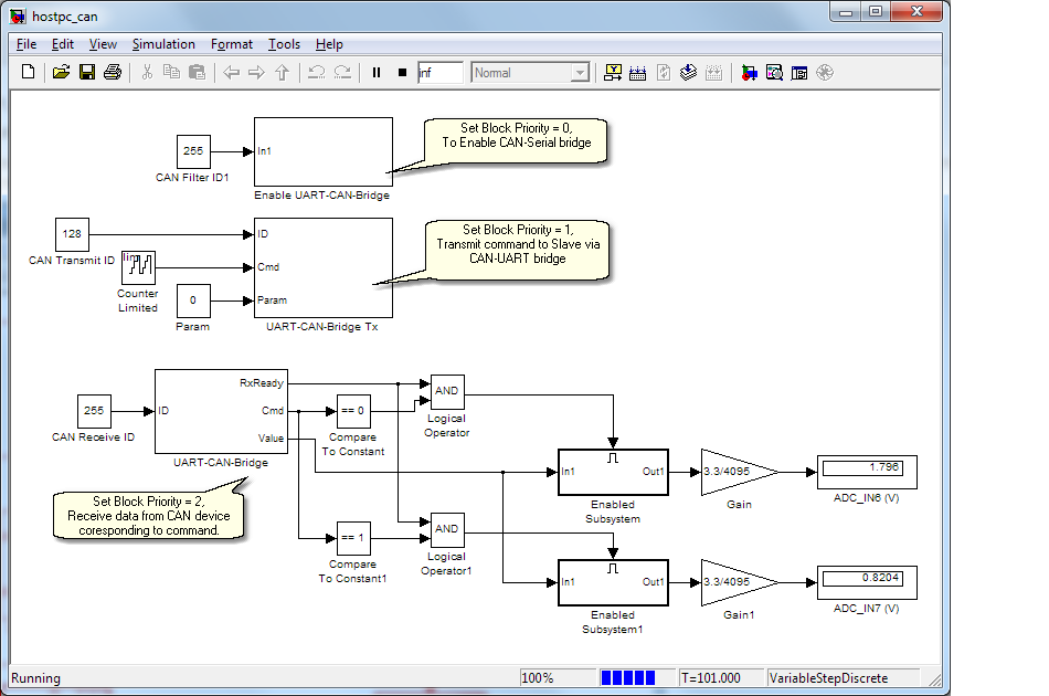
This model is a demo of CAN slave device node operating on the bus. It's receive CAN packet sent by master, then response ADC measurement value via CAN message to master.
File: stm32f0_can_serial_bridge_binary.mdl
File: hostpc_can.mdl
To improve Tx and Rx speed, follow the Latency_time_setting instruction. Run simulation, Display block now showing the reading value (ADC_IN6 and ADC_IN7).