|
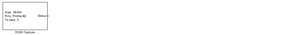
<< Click to Display Table of Contents >> DCMI Capture |
  
|
|
<< Click to Display Table of Contents >> DCMI Capture |
|
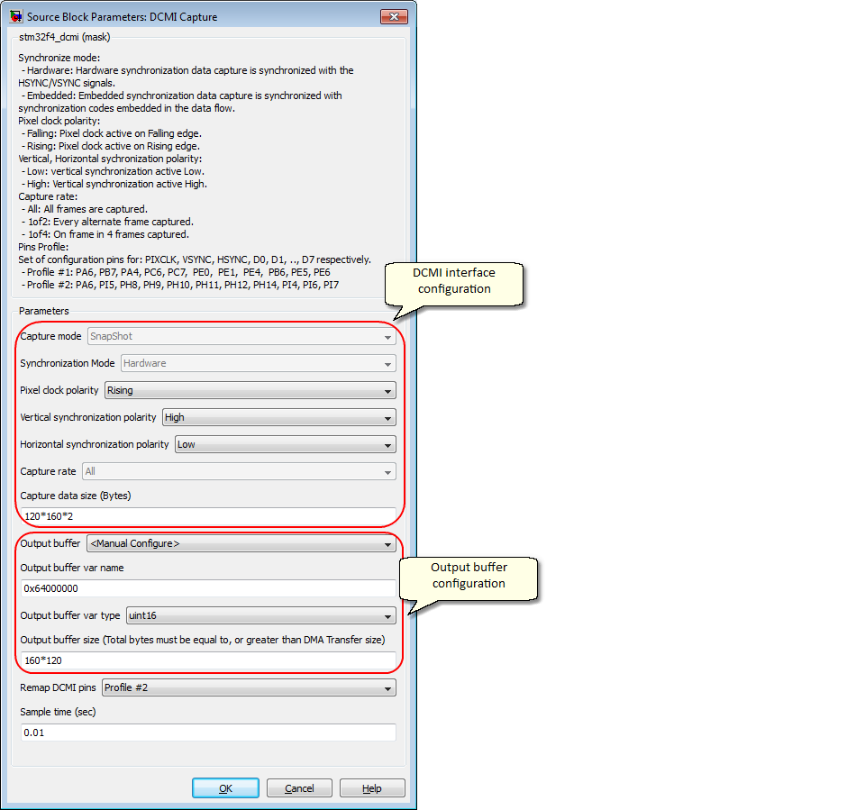
Configuration item |
Selectable option/ Value |
Description |
Capture mode |
Snapshot | Continuous |
Note: support Snapshot mode only. |
Synchronization mode |
Hardware | Embedded |
- Hardware: Hardware synchronization data capture is synchronized with the HSYNC/VSYNC signals. - Embedded: Embedded synchronization data capture is synchronized with synchronization codes embedded in the data flow. Note: support Hardware mode only. |
Pixel clock polarity |
Rising | Falling |
- Falling: Pixel clock active on Falling edge. - Rising: Pixel clock active on Rising edge. |
Vertical synchronization polarity |
High | Low |
- Low: vertical synchronization active Low. - High: Vertical synchronization active High. |
Horizontal synchronization polarity |
High | Low |
- Low: vertical synchronization active Low. - High: Vertical synchronization active High. |
Capture rate |
All | 1of2 | 1of4 |
- All: All frames are captured. - 1of2: Every alternate frame captured. - 1of4: On frame in 4 frames captured. |
Capture data size (Bytes) |
(Specify number of data bytes to capture) |
The number of data (in bytes) to transfer for DMA. It is depend on image size and color format. For example: To capture image size 160 x 120, and the pixel color is 16bits (RGB565). Data size (bytes) = 160 * 120 * 2 |
Output buffer |
- |
Note: The current release require manual configure. |
Output buffer var name |
(Specify output buffer name) |
Note: support specify the external memory address. |
Output buffer var type |
double | single | int8 | uint8 | int16 | uint16| int32 | uint32 |
Note: This configuration is use for configure the DMA memory data size. Use uint16 for 16bit external memory (1024 x 16 or 512 x 16). |
Output buffer size |
(Specify size of output buffer) |
This configuration is for validation only (not effect to code generation), to make sure the buffer have sufficient space for storing data. |
Remap DCMI pins |
Profile #1 | Profile #2 |
This is pin set configuration. Profile #1: for low pin count, example: F4DISCOVERY board. Profile #2: for more pin count MCU, example: FiO2 board. |
Sample time (sec) |
(Specify sample time) |
For example, Sample time 0.01 for 10Hz capture rate. |
Status, this port indicates the status of capture. Return 0 if capture is success, otherwise fail.
Use this block to receive picture from DCMI camera device.