|
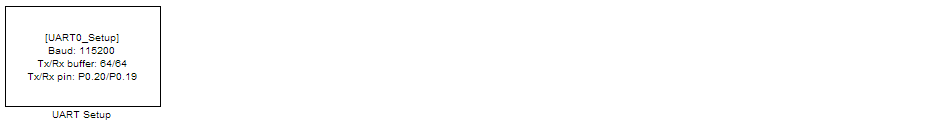
<< Click to Display Table of Contents >> UART Setup |
  
|
|
<< Click to Display Table of Contents >> UART Setup |
|
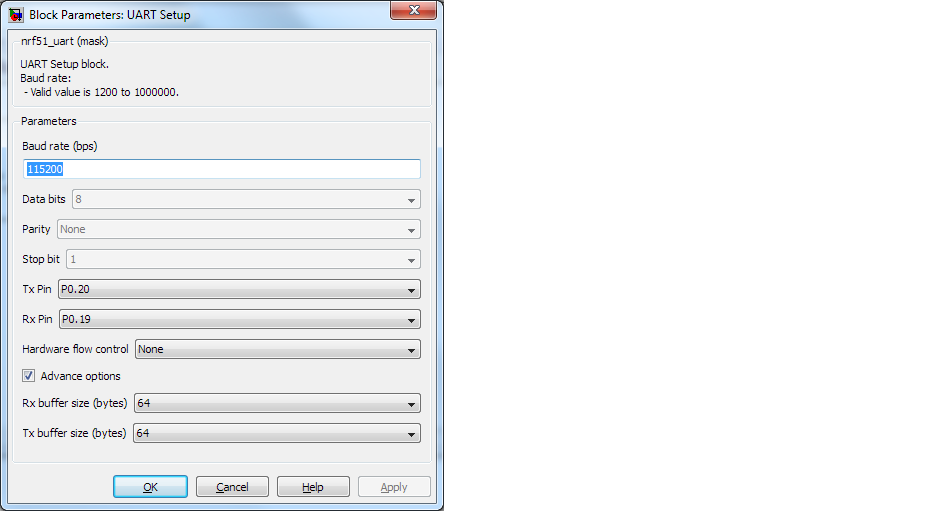
Configuration item |
Selectable option/ Value |
Description |
|---|---|---|
Baud rate (bps) |
communication speed configuration value, Example: 9600, 115200 or 1000000 |
|
Data bits |
8 |
For latest version release of blockset support only 8 data bits |
Parity |
None |
|
Stop bit |
1 |
|
Tx Pin |
Pin connect (remap) configuration for transmit pin (Tx). Or select "Not used " to disable Tx for the selected module |
The UART Tx signal will be transmitted to other device at selected pin |
Rx Pin |
Pin connect (remap) configuration for transmit pin (Rx). Or select "Not used " to disable Rx for the selected module |
The UART Rx signal will be received from other device via selected pin |
Hardware flow control |
None| RTS/CTS |
None - to disable hardware flow control RTS/CTS - to enable both RTS and CTS for hardware flow control |
HW flow control, CTS Pin |
Pin connect (remap) configuration for transmit pin (CTS) |
The output signal CTS can be configured to control at selected pin |
HW flow control, RTS Pin |
Pin connect (remap) configuration for transmit pin (RTS) |
The input signal RTS can be configured to receive by selected pin |
Advance options |
Checked| Unchecked |
This option is to enable advance configuration mode, include memory buffer size. |
Rx buffer size (bytes) |
16| 32|64|128| 256| 512 | 1024 |
Select buffer size for receiving (Rx) buffer, size must be in a number of 2^N and higher than packet length. Example, to receive Rx packet with length 90 bytes, the Rx buffer can be configure to 128 or higher. |
Tx buffer size (bytes) |
16| 32|64|128| 256| 512 | 1024 |
Similar to Rx buffer, size must be in a number of 2^N and higher than transmit packet length. |