|
<< Click to Display Table of Contents >> Introduction |
  
|
|
<< Click to Display Table of Contents >> Introduction |
|
Although this decade commonly known as the digital age, analog circuits are still used in many cases. In order to use them most effectively, circuit designers need to understand analog signals, methodologies to use or apply them, as well as analog components.
This article introduces basic aspects of operational amplifier (Op-Amp) which designers need to know to be able to use them from the most basic to advanced applications.
The operational amplifier (Op-Amp) is one of the most fundamentally useful and important components of analog electronics devices. They are used in a vast array of consumer, industrial, and scientific devices, as shown below.

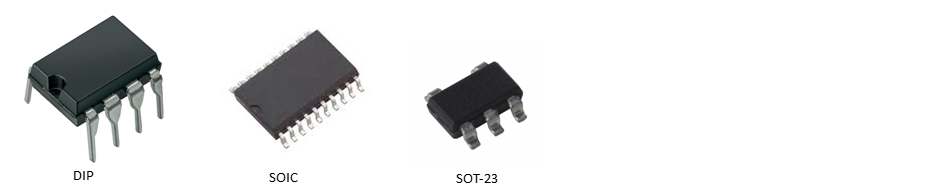
Op-Amp was first invented during the time of the Second World War. So, Op-Amps are not new. The Op-Amp have many package type such as DIP, SOIC, SOT-23, etc.
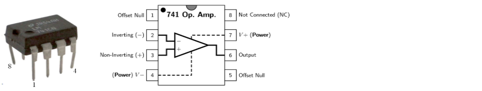
For examples, the following picture shows one of the most popular op-amp, LM741 with 8 pins dip package and its internal schematic.
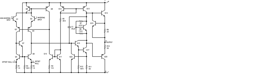
The internal circuitry of LM741 consists of many type electronics device, passive, active, and semiconductor, all integrated together.
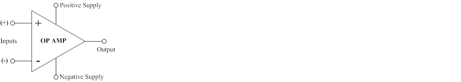
The following picture shows symbol for Op-Amp, composing two differential input, one output, positive and negative power supply.
Conceptually, Op-Amp is used to produces an output voltage that is the difference between the two input terminals multiply by the gain.
1) The input impedance is infinite - i.e. no current ever flows into either input of the op-amp.
2) The output impedance is zero - i.e. the op-amp can drive any load impedance to any voltage.
3) The open-loop gain (A) is infinite.
4) The bandwidth is infinite.
5) The output voltage is zero when the input voltage difference is zero.
1) The input impedance is about 106 to 1013 Ω.
2) The output impedance is about 10 to 100 Ω.
3) The open-loop gain (A) is 105 to 108.
4) The bandwidth is limited.
5) The output voltage is not zero although the input voltage difference is zero.
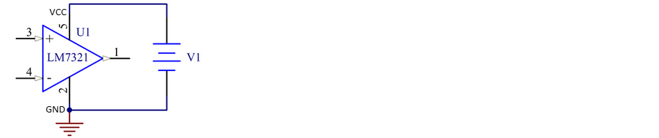
OP-AMP POWER SUPPLY
All Op-Amp have two power pins. In most cases, they are labeled VCC and VSS, but sometimes they are labeled VCC and GND. Most analog designers must know how to use Op-Amp with a dual or single power supply. A brief summary, the single-power supply circuit is for DC input signal, and the dual-power supply circuit is suit for AC signal.
A single-supply circuit connects the Op-Amp power pins to a positive voltage and ground. The positive voltage is connected to VCC and ground is connected to VSS or GND.
A dual power supply consists of a positive supply and an equal and opposite negative supply . The most common values are ±15 V, but ±12 V and ±5 V are also used. The input and output voltages are referenced to ground. The output voltage is swing both positive and negative but limited to either the upper or lower power supply rail.

Tip For dual power supply, it is possible to adapt from the following single power supply circuit. This circuit helps to save components and cost. Normally, the value of R1 = R2, and C1 = C2. The current is limited by the value of R1 and R2 where Iout = V1/(R1+R2).
