|
<< Click to Display Table of Contents >> PWM Capture |
  
|
|
<< Click to Display Table of Contents >> PWM Capture |
|
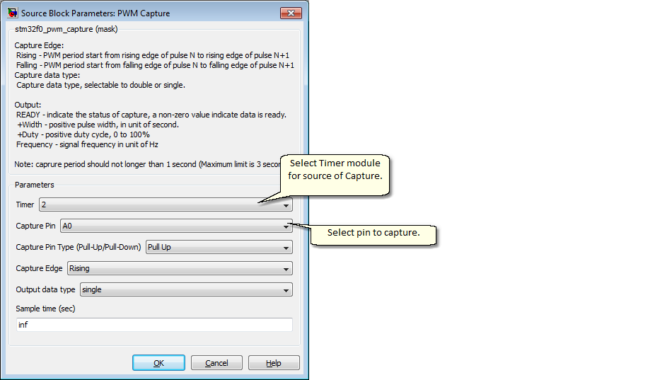
Configuration item |
Selectable option/ Value |
Description |
Timer |
(Select time module for available list) |
List of timers available depending on MCU part |
Capture pin |
(Select Pin for capture) |
Note: available pin for selection depending on selected timer module. |
Capture Pin Type (Pull-Up/Pull-Down) |
None | Pull Up | Pull Down |
Pin type for select capture pin |
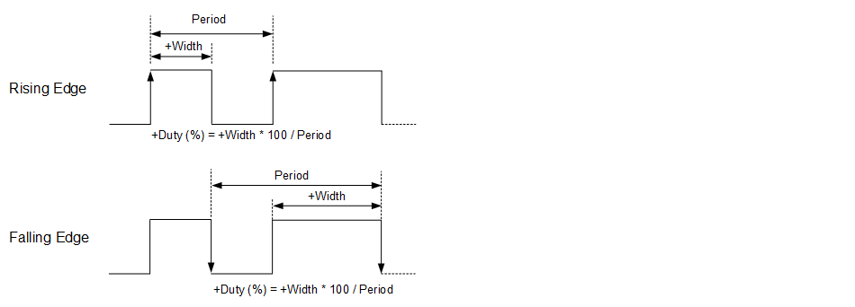
Capture Edge |
Rising | Falling |
|
Capture data type |
double | single |
Recommended use "single" for data type, to optimize math calculation code. |
Sample time (sec) |
(sampletime) |
Specify block sample time |
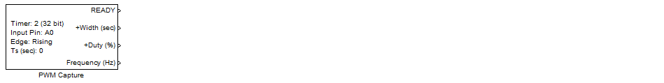
Return status of PWM capture operation, value is non-zero when data is ready.
Positive pulse width value, in unit of seconds.
Positive duty cycle value, in percentage.
PWM frequency, in unit of Hz.
Use this block when input signal is PWM, to analyze its frequency and duty cycle. Maximum input frequency should lower than 10kHz, and minimum is 0.33Hz.
1. Selected timer module must not conflicted with other timer function.
2. Selectable pin for capture the input signal (available pins depending of selected Timer module).
3. The block use input capture interrupt approach, it may effect to overall system timing if input frequency too High (Lower than 10kHz is recommended).