|
<< Click to Display Table of Contents >> Basic PWM |
  
|
|
<< Click to Display Table of Contents >> Basic PWM |
|
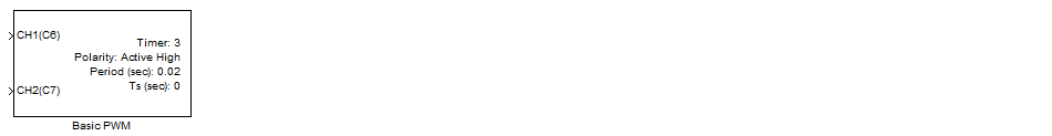
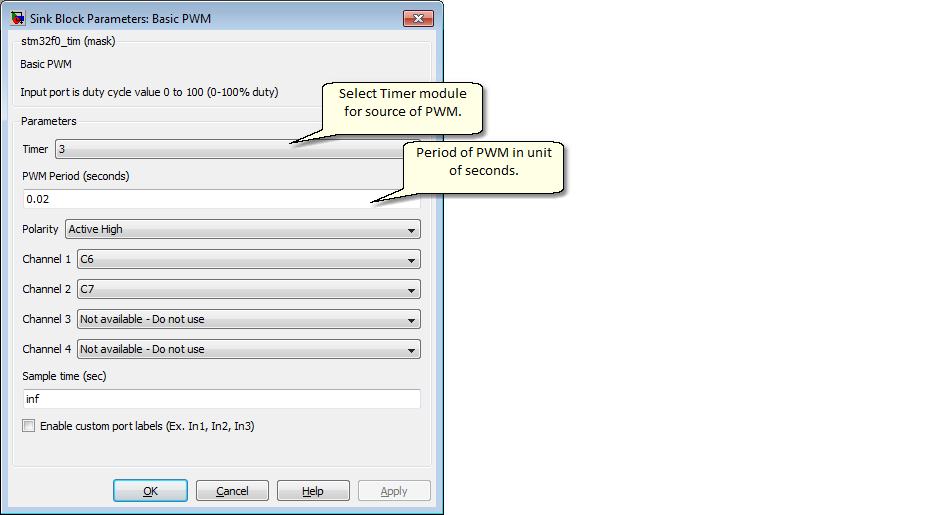
Configuration item |
Selectable option/ Value |
Description |
Timer |
(Select time module for available list) |
List of timers available depending on MCU part |
PWM Period (seconds) |
(Specify period value of PWM pulse) |
Note: Period (sec) = 1/Frequency (Hz) |
Polarity |
Active High | Active Low |
Specify Positive or Negative PWM pulse |
Channel 1 |
(Select Pin for PWM channel 1) |
|
Channel 2 |
(Select Pin for PWM channel 2) |
|
Channel 3 |
(Select Pin for PWM channel 3) |
|
Channel 4 |
(Select Pin for PWM channel 4) |
|
Sample Time (Sec) |
(sampletime) |
Specify block sample time. |
For application which need to encode a data value into PWM signal, for interface with external hardware circuit.
| 1. |