|
<< Click to Display Table of Contents >> UART Rx |
  
|
|
<< Click to Display Table of Contents >> UART Rx |
|
Configuration item |
Selectable option/ Value |
Description |
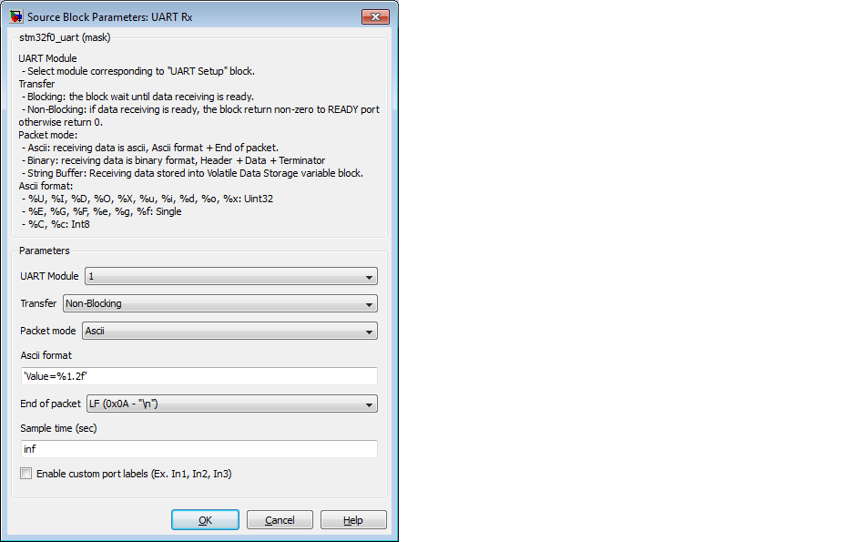
UART Module |
1| 2| 3| 4 |
Select UART/ USART module to receive the Rx data from |
Transfer mode |
Blocking| Non-Blocking Note: This configuration mode is "Blocking" |
Blocking: The CPU process will wait for data until full packet received, then exit the Rx block to continue execute the other block. This mode is suitable for real-time processing with HIL. Non-Block: This configuration is working as asynchronous (software interrupt or callback), the output of Rx block for this mode is call-back to Function-call subsystem. |
Packet mode |
Binary| Ascii| String Buffer Note: This configuration is "Ascii" |
Binary: This packet mode is will accept the packet contains binary data, by specify the Header, Data format and Terminator of a packet to receive. The block will not accept the packet which contains invalid Header or Terminator. Ascii: This packet mode will accept the packet contains ascii data (string), by specify the sscanf format. The block will create the output port corresponding to the sscanf % format. Example: for packet format "Value=%d", the output port of block will be uint32. If packet "Value=100" is received, the the block will return 100 to output port of block. String Buffer: This packet mode is receive the raw string data and store into string buffer directly without processing the packet. |
Format |
Ascii format pattern for sscanf Example: "Value=%d" |
Scanf format specifier, start with %. Below is supported by block. %u, %i, %d, %o, %x : sscanf output will be type of uint32 %e, %g, %f : sscanf output will be type of single %s : sscanf output will be type of string. Note: output buffer of %s will be limit to 127 charactor maximum, so recommended to use %127s instead of %s. %c : sscanf output will return int8 |
Terminator |
LF| CR| CRLF (Specify the terminator pattern of packet to receive)
|
Terminator in ascii mode is used for detect the end of packet. The block will continue receive ascii and store in a buffer, and detect terminator in the same time. After found and match terminator, the block will perform sscanf function to extract the value in a packet. |
Sample Time (sec) |
Sample time configuration of a block |
Configuration item |
Selectable option/ Value |
Description |
UART Module |
1| 2| 3| 4 |
Select UART/ USART module to receive the Rx data from |
Transfer mode |
Blocking| Non-Blocking Note: This configuration mode is "Blocking" |
Blocking: The CPU process will wait for data until full packet received, then exit the Rx block to continue execute the other block. This mode is suitable for real-time processing with HIL. Non-Block: This configuration is working as asynchronous (software interrupt or callback), the output of Rx block for this mode is call-back to Function-call subsystem. |
Packet mode |
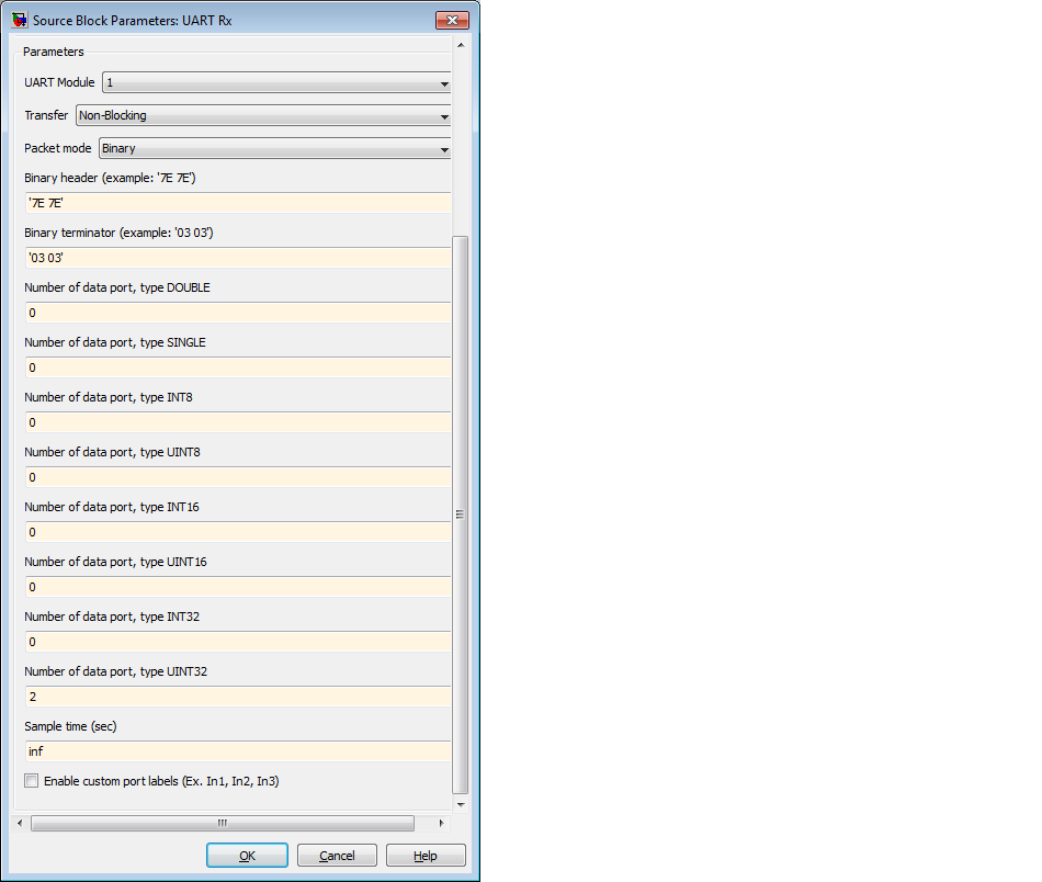
Binary| Ascii| String Buffer Note: This configuration is "Binary" |
Binary: This packet mode is will accept the packet contains binary data, by specify the Header, Data format and Terminator of a packet to receive. The block will not accept the packet which contains invalid Header or Terminator. Ascii: This packet mode will accept the packet contains ascii data (string), by specify the sscanf format. The block will create the output port corresponding to the sscanf % format. Example: for packet format "Value=%d", the output port of block will be uint32. If packet "Value=100" is received, the the block will return 100 to output port of block. String Buffer: This packet mode is receive the raw string data and store into string buffer directly without processing the packet. |
Header |
(Specify the Header pattern of packet to receive) Example: If a packet contains 2 bytes of header, [0x7E 0x7E] |
This header is used for packet synchronization, the block will continue search for header, once header is matched then next bytes will be data. |
Number of data port, type DOUBLE |
(Number of data type double in packet) |
1 data port of this data type is combined from 8bytes in packet. |
Number of data port, type SINGLE |
(Number of data type single in packet) |
1 data port of this data type is combined from 4bytes in packet. |
Number of data port, type INT8 |
(Number of data type int8 in packet) |
1 data port of this data type is combined from 1byte in packet. |
Number of data port, type UINT8 |
(Number of data type uint8 in packet) |
1 data port of this data type is combined from 1byte in packet. |
Number of data port, type INT16 |
(Number of data type int16 in packet) |
1 data port of this data type is combined from 2bytes in packet. |
Number of data port, type UINT16 |
(Number of data type uint16 in packet) |
1 data port of this data type is combined from 2bytes in packet. |
Number of data port, type INT32 |
(Number of data type int32 in packet) |
1 data port of this data type is combined from 4bytes in packet. |
Number of data port, type UINT32 |
(Number of data type uint32 in packet) |
1 data port of this data type is combined from 4bytes in packet. |
Terminator |
(Specify the terminator pattern of packet to receive) Example: If a packet contains 2 bytes of terminator, [0x03 0x03] |
This terminator is used for packet validation, once header is matched and all data types are received, the next bytes will be terminator. if terminator is not matched, the block will reject the previous bytes (Header and data), and continue searching for new packet start with header again. |
Sample Time (sec) |
Sample time configuration of a block |
Configuration item |
Selectable option/ Value |
Description |
UART Module |
1| 2| 3| 4 |
Select UART/ USART module to receive the Rx data from |
Transfer mode |
Blocking| Non-Blocking Note: This configuration mode is "Blocking" |
Blocking: The CPU process will wait for data until full packet received, then exit the Rx block to continue execute the other block. This mode is suitable for real-time processing with HIL. Non-Block: This configuration is working as asynchronous (software interrupt or callback), the output of Rx block for this mode is call-back to Function-call subsystem. |
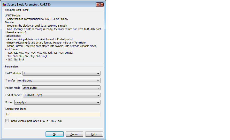
Packet mode |
Binary| Ascii| String Buffer Note: This configuration is "String Buffer" |
Binary: This packet mode is will accept the packet contains binary data, by specify the Header, Data format and Terminator of a packet to receive. The block will not accept the packet which contains invalid Header or Terminator. Ascii: This packet mode will accept the packet contains ascii data (string), by specify the sscanf format. The block will create the output port corresponding to the sscanf % format. Example: for packet format "Value=%d", the output port of block will be uint32. If packet "Value=100" is received, the the block will return 100 to output port of block. String Buffer: This packet mode is receive the raw string data and store into string buffer directly without processing the packet. |
Buffer |
Select String Buffer name to store the receiving packet |
Note: The buffer name will available for selection when drop the volatile data storage block with configure type as string. |
Terminator |
LF| CR| CRLF (Specify the terminator pattern of packet to receive)
|
Terminator in ascii mode is used for detect the end of packet. The block will continue receive ascii and store in a buffer, and detect terminator in the same time. After found and match terminator, the block will perform copy the packet to the specified string buffer. |
Sample Time (sec) |
Sample time configuration of a block |
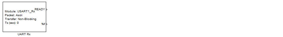
This configuration mode is similar to the previous mode except for the addition of an output port "READY". This port will output:
| A value of 1 when a new data packet becomes available. |
| A value of 0 when new data is not available. |
Received data from a Non-Blocking UART RX Block may be processed in an Enable Subsystem where READY signal is used to enable the subsystem. For example usage of non-blocking mode see Two boards communication, non-blocking mode demo.
Use this block to receive data from UART when application need communication between device to device via UART protocol.
The block will get the data from selected UART module buffer (DMA Rx buffer), then processing the packet. By using DMA feature, the received bytes will store into buffer automatically while CPU busy with other block in same time step without losing bytes.