|
<< Click to Display Table of Contents >> Digital Output |
  
|
|
<< Click to Display Table of Contents >> Digital Output |
|
Demo File: stm32f4_digital_output_demo.mdl
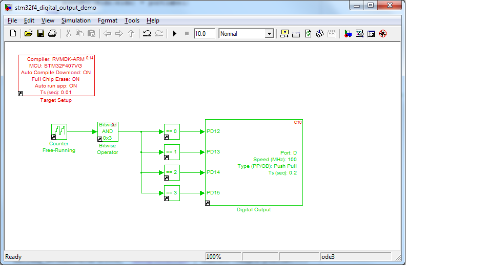
This example shows how to use the Digital Output Block.
It uses the Simulink Pulse Generator Block to control 4 LEDs to turn on and off repeatedly.
When running the demo with the STM32F4DISCOVERY Board, you should see LEDs turn on and off with following sequence with 200ms per state.
State1: LED1 ON, all other OFF.
State2: LED2 ON, all other OFF.
State3: LED3 ON, all other OFF.
State4: LED4 ON, all other OFF.
Repeat all state.