|
<< Click to Display Table of Contents >> I2C Master Read/Write |
  
|
|
<< Click to Display Table of Contents >> I2C Master Read/Write |
|
Configuration item |
Selectable option/ Value |
Description |
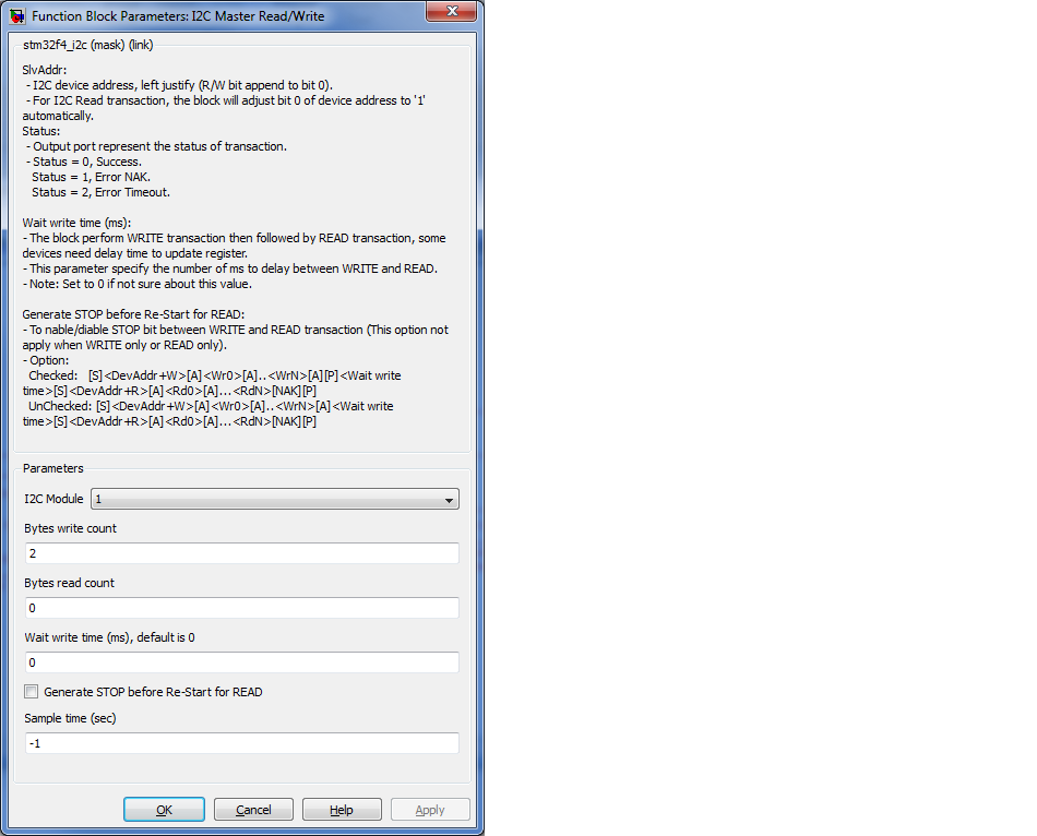
I2C Module |
1 | 2 | 3 |
Select I2C module for Read/ Write transaction. |
Bytes write count |
(Positive number) |
Specify number of bytes to write to I2C in a transaction. This number including command bytes but not include slave address. |
Bytes read count |
(Positive number) |
Specify number of bytes to read from I2C in a transaction. |
Wait write time (ms) |
(Positive number) |
This delay time is optional, can be used for add some delay after write a value to I2C before process next transaction. Warning: this wait time is blocking delay, it may slow down overall process. |
Generate STOP before Re-START for READ |
Checked | Unchecked |
Optional, for device which not support random read format. |
Sample time (sec) |
-1 (Inherited) or specify. |
Specify sample time for this block. |
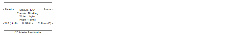
1. SlvAddr, input the device address in left justify format (shift 7 bit address 1 bit to left).
2. Data to write to I2C.
1. Status, indicate status of I2C transaction.
1.1 Status 0 indicates success,
1.2 Status 1 - NAK. Slave device did not acknowledge, mostly can be from Address not match or Slave not connected.
1.3 Status 2- TIMEOUT. Communication timeout, mostly from I2C bus is low longer than timeout setting. Since I2C port is open drain, missing Pull-up resister can cause I2C bus low.
2. Data reading from device, valid only when Status is success.