|
<< Click to Display Table of Contents >> UART Setup |
  
|
|
<< Click to Display Table of Contents >> UART Setup |
|
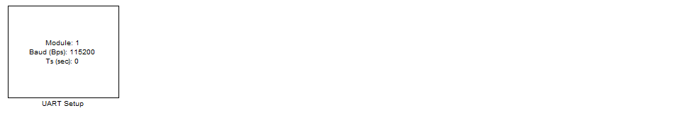
The UART Setup block can be found on Library browser "Wajung Blockset" -> "STM32F4 Target" -> "On-chip Peripherals" -> "UART"
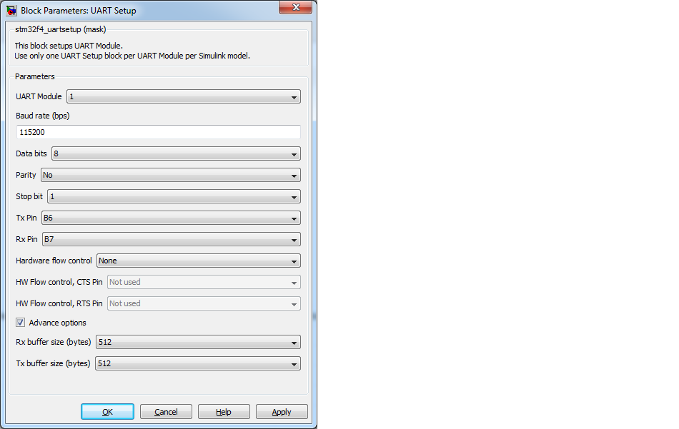
Configuration item |
Selectable option/ Value |
Description |
UART Module |
1| 2| 3| 4| 5| 6 |
Select UART/ USART module for the configuration |
Baud rate (bps) |
communication speed configuration value, Example: 9600, 115200 or 1000000 |
For module 1 and module 6 can be set up to 10.5Mbps (max), and other module 2, 3, 4, 5 can set up to 5.25Mbps (max) |
Data bits |
8 |
For latest version release of blockset support only 8 data bits |
Parity |
None| Odd| Even |
Parity bit selection |
Stop bit |
0.5| 1| 1.5| 2 |
Stop bit selection |
Tx Pin |
Pin connect (remap) configuration for transmit pin (Tx). Or select "Not used " to disable Tx for the selected module |
The UART Tx signal will be transmitted to other device at selected pin |
Rx Pin |
Pin connect (remap) configuration for transmit pin (Rx). Or select "Not used " to disable Rx for the selected module |
The UART Rx signal will be received from other device via selected pin |
Hardware flow control |
None| RTS| CTS| RTS/CTS |
This configuration available only UART with synchronous module 1, 2, 3 and 6. For module 4 and 5, this option will be automatic set to None. Note: None - to disable hardware flow control RTS - to enable RTS for hardware flow control CTS - to ebable CTS for hardware flow control RTS/CTS - to enable both RTS and CTS for hardware flow control |
HW flow control, CTS Pin |
Pin connect (remap) configuration for transmit pin (CTS) |
The output signal CTS can be configured to control at selected pin |
HW flow control, RTS Pin |
Pin connect (remap) configuration for transmit pin (RTS) |
The input signal RTS can be configured to receive by selected pin |
Advance options |
Checked| Unchecked |
This option is to enable advance configuration mode, include memory buffer size. |
Rx buffer size (bytes) |
16| 32|64|128| 256| 512| 1024| 2048 |
Select buffer size for receiving (Rx) buffer, size must be in a number of 2^N and higher than packet length. Example, to receive Rx packet with length 90 bytes, the Rx buffer can be configure to 128 or higher. |
Tx buffer size (bytes) |
16| 32|64|128| 256| 512| 1024| 2048 |
Similar to Rx buffer, size must be in a number of 2^N and higher than transmit packet length. |
The block must be placed into a simulink model to enable/ configure the selected UART module when the application need to send or receive data from external device using UART protocol.
This block will perform configuration as below;
1. Enable GPIO clock using by Tx, Rx, RTS and CTS.
2. Configure remap pin for Tx, Rx, RTS and CTS.
3. Enable module clock for selected UART/ USART module.
4. Setup parameters for communication module.
5. Enable DMA clock.
6. Configuration for DMA transfer for Tx and Rx.