|
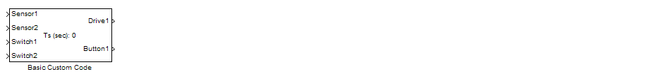
<< Click to Display Table of Contents >> Basic Custom Code |
  
|
|
<< Click to Display Table of Contents >> Basic Custom Code |
|
When you want to add your own custom C code to the system.
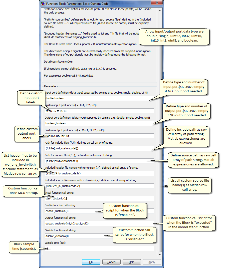
| 1. | Define input / output ports for the Block. |
2. Define include and source paths/files for the custom code.
3. Define three function prototypes: enable, output, disable.
The number of ports equal the number of elements defined in the "Input port definition (data type) separated by comma e.g. double, single, double, uint8" and "Output port definition (data type) separated by comma e.g. double, single, double, uint8" editbox. Separate each element with a comma. The top port correspond to the first defined data type.
Leave the editbox empty if ports are not required.
Support signal data types are
| o | double |
| o | single |
| o | uint32 |
| o | int32 |
| o | uint16 |
| o | int16 |
| o | uint8 |
| o | int8 |
| o | boolean |
Port labels can be defined in the Custom input / output port labels editboxes i.e. "Custom input port labels (Ex. In1, In2, In3)" and "Custom output port labels (Ex. Out1, Out2, Out3)".
Input and Output signals can be either scalar, vector, or 2-D matrix type.
The dimensions of input signals are automatically inherited from the supplied input signals.
The dimensions of output signals must be implicitly defined using the following format.
DataType:nRowsxnCols
For examples: double:4x5,int8,int16:3x1. If dimensions are not defined, scalar signal (1x1) is assumed. See the following for using the Basic Custom Code Block with non-scalar signals.
"Path for include files (*.h), defined as cell array of string." editbox accepts Matlab row cell array of string. All header files (*.h) present in the declared include path will be used during the build process. This parameter tells Matlab where to look for header files.
"Path for source files (*.c), defined as cell array of string." editbox accepts Matlab row cell array of string. All source files (*.c) present in the declared include path will be used during the build process. This parameter tells Matlab where to look for source files.
"Path for source files (*.c), defined as cell array of string." editbox accepts Matlab row cell array of string. All source files (*.c) present in the declared include path will be used during the build process. This parameter tells Matlab where to look for source files.
"Included header file names with extension (.h), defined as cell array of string." editbox accepts Matlab row cell array of string. Header files (*.h) present in this editbox will added in waijung_hwdrvlib.h as #include statement. Declare each source file name with and extension .h.
"Included source file names with extension (.c), defined as cell array of string." editbox accepts Matlab row cell array of string. Source files (*.c) present in this editbox will be included in the build process. Declare each source file name with and extension .c.
After code generation, each Simulink block must have at least three functions that are called at different point of time during target system execution. These are:
An initial function will be called once at MCU start-up.
An enable function will be called at system initialization and every time the block is enabled, e.g. in a case where a block is located in an Enabled Subsystem.
An output function will be called every time step to compute output values.
A disable function will be called at system termination and every time the block is disabled, e.g. in a case where a block is located in an Enabled Subsystem.
The code generation mechanism generates correct function prototypes and function calls for each block automatically. Your job is to define function prototypes that are wrapped inside these automatically-generated Matlab function calls.
The Enable function can be defined in "Enable function call string" editbox.
The Disable function can be defined in "Disable function call string" editbox.
The Enable function and Disable function must not have any parameters. These function will be called every time the system is initialized/terminated and enabled/disabled.
The output function require input and output (scalar) signal to be declared as parameter of the output function.
Name convention for custom code output function parameters
The parameters for custom code output function must follow the following requirements.
| a. | Always start with input (if any) and follow by output (if any). |
| b. | Use in### and out### for input and output signal respectively, where ### represent digits starting from 1. |
For examples
The block has 2 inputs and 3 outputs, output function prototype is void custom_output_function_name(in1,in2,out1,out2,out3);
The block has 0 inputs and 3 outputs, output function prototype is void custom_output_function_name(out1,out2,out3);
The block has 2 inputs and 0 outputs, output function prototype is void custom_output_function_name(in1,in2);