|
<< Click to Display Table of Contents >> Zero-Span |
  
|
|
<< Click to Display Table of Contents >> Zero-Span |
|
The zero and span circuit is frequently used in instrumentation and measurement processes. This circuit adjust the slope and zero point of the signal which correlation between input and output.
A linear op amp transfer function is limited to the equation of a straight line (Eq1)
y = +-mx +- b (1)
The equation of a straight line has four possible solutions depending upon the sign of m (slope) and b (intercept), thus the equations yield solutions in four forms.
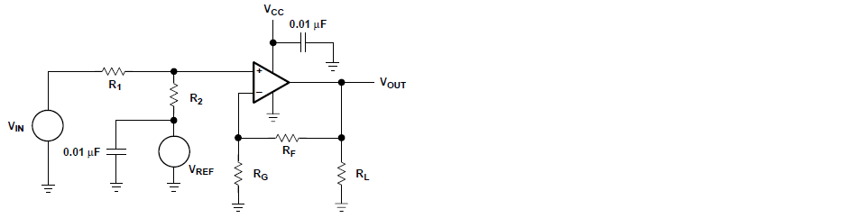
CASE1: Vout = +mVin + b (2)
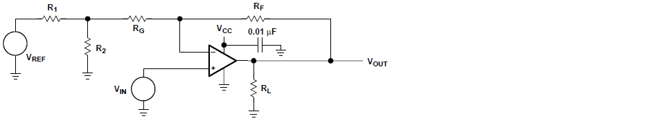
CASE2: Vout = +mVin - b (3)
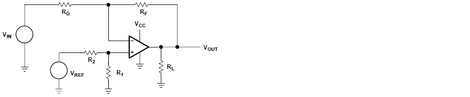
CASE3: Vout = -mVin + b (4)
CASE4: Vout = -mVin - b (5)

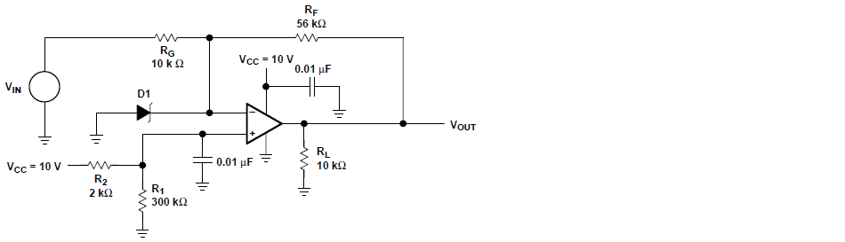
Example: Given a set of two data points for Vout and Vin, and equations are solved to determine m and b for the equation that satisfies the given data; i. e., a sensor output signal ranging from 0.1 V to 0.2 V must be interfaced into an analog-to-digital converter that has an input voltage range of 1 V to 4 V.
These data points (Vout = 1 V @ Vin = 0.1 V, Vout = 4 V @ Vin = 0.2 V) are inserted into Equation 2 (CASE 1), to obtain m and b for the specifications.
1 = m(0.1) + b (6)
4 = m(0.2) + b (7)
After algebraic manipulation of Equation 6, 7, yield the solution, m = 30 and b = -2.
Now m and b are rewrite to new equation.
Vout = 30Vin - 2 (8)
The equation (8) similar to the CASE2: Vout = +mVin - b circuit. The next step required to complete the problem solution is to develop a circuit that has an m = 30 and b = –2 (CASE 2).
As mentioned all above are the preliminary to understand more complex of op-amp design technique, zero-span circuits are use to the examples to solve the complexities of analog signal conditioning problems. For more details, you can study from the references [4].