|
<< Click to Display Table of Contents >> Character LCD Setup |
  
|
|
<< Click to Display Table of Contents >> Character LCD Setup |
  
|


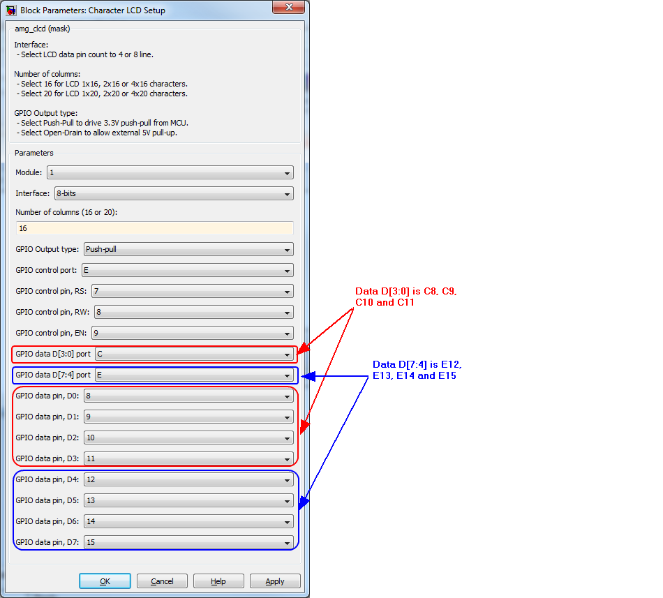
The block located at Waijung Blockset/ Hardware Modules/ Charactor LCD
Configuration item |
Selectable option/ Value |
Description |
Module |
1| 2| 3| 4 |
Select CLCD module number, allow up to 4 LCD running in same model. |
Interface |
4-bits| 8-bits |
4-bit: Data pin D4, D5, D6, D7 are required for interfacing with CLCD. 8-bit: Data pin D0, D1, D2, D3, D4, D5, D6, D7 are required for interfacing with CLCD. |
Number of lines |
Example: 1, 2, 3 or 4 |
Specify number of line supported by LCD. |
Number of columns |
Example: 16 or 20 |
Specify number of columns supported by LCD. |
GPIO Output type |
Push-Pull| Open-Drain |
Depending on circuit of signal connection to LCD, pin can be configure to Open-Drain of external pull-up resister available, otherwise using Push-pull. |
GPIO control port |
A| B| C| D| E| F| G| H| I |
Select GPIO port for control signal: RS, RW and EN. |
GPIO control pin, RS |
0| 1| 2| 3| 4| 5| 6| 7| 8| 9| 10| 11| 12| 13| 14| 15 |
Select GPIO pin for control signal RS. |
GPIO control pin, RW |
0| 1| 2| 3| 4| 5| 6| 7| 8| 9| 10| 11| 12| 13| 14| 15 |
Select GPIO pin for control signal RW. |
GPIO control pin, EN |
0| 1| 2| 3| 4| 5| 6| 7| 8| 9| 10| 11| 12| 13| 14| 15 |
Select GPIO pin for control signal EN. |
GPIO data D[3:0] port |
A| B| C| D| E| F| G| H| I |
Select GPIO port for data signal: D0, D1, D2 and D3. |
GPIO data D[7:4] port |
A| B| C| D| E| F| G| H| I |
Select GPIO port for data signal: D4, D5, D6 and D7. |
GPIO data pin, D0 |
0| 1| 2| 3| 4| 5| 6| 7| 8| 9| 10| 11| 12| 13| 14| 15 |
Select GPIO pin for data signal, D0. |
GPIO data pin, D1 |
0| 1| 2| 3| 4| 5| 6| 7| 8| 9| 10| 11| 12| 13| 14| 15 |
Select GPIO pin for data signal, D1. |
GPIO data pin, D2 |
0| 1| 2| 3| 4| 5| 6| 7| 8| 9| 10| 11| 12| 13| 14| 15 |
Select GPIO pin for data signal, D2. |
GPIO data pin, D3 |
0| 1| 2| 3| 4| 5| 6| 7| 8| 9| 10| 11| 12| 13| 14| 15 |
Select GPIO pin for data signal, D3. |
GPIO data pin, D4 |
0| 1| 2| 3| 4| 5| 6| 7| 8| 9| 10| 11| 12| 13| 14| 15 |
Select GPIO pin for data signal, D4. |
GPIO data pin, D5 |
0| 1| 2| 3| 4| 5| 6| 7| 8| 9| 10| 11| 12| 13| 14| 15 |
Select GPIO pin for data signal, D5. |
GPIO data pin, D6 |
0| 1| 2| 3| 4| 5| 6| 7| 8| 9| 10| 11| 12| 13| 14| 15 |
Select GPIO pin for data signal, D6. |
GPIO data pin, D7 |
0| 1| 2| 3| 4| 5| 6| 7| 8| 9| 10| 11| 12| 13| 14| 15 |
Select GPIO pin for data signal, D7. |
Use this block for Character LCD module configuration, to configure control pins and data pins.
LCD processing is designed to not to load too much on CPU. It calculate timing required for LCD control, for example when system sample time is less tan 0.0005 seconds, LCD load is less than 0.000010 seconds per step. And when system sample time more than 0.0005 seconds, LCD load is (Sample_time/0.0005)*0.000060 seconds per step.
This block, "Character LCD Setup" work as background processing task for character LCD display control, and Pins configuration. It is designed as non-blocking process and adaptive timing control to avoid too much loading on overall control process.