|
<< Click to Display Table of Contents >> Amplification |
  
|
|
<< Click to Display Table of Contents >> Amplification |
|
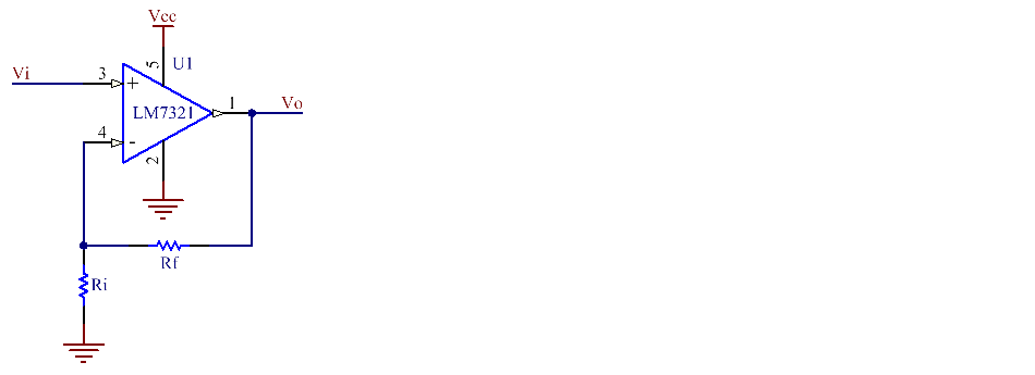
The amplifier circuit is used to increase the amplitude of input signal. For example, we want the output voltage at 10V but the input is only 3V.
The circuit diagram depict below is basic circuit of amplification. This circuit is non-inverting amplifier, the input voltage signal, ( Vi ) is applied directly to the non-inverting ( + ) input terminal which means that the output signal is "in-phase" with the input signal. The Rf resistor feedback signal from output to inverting input and Ri pulling the inverting input down to GND. The value of resistor can calculate by:
Vo/Vi = 1+(Rf/Ri)
The following examples show how to configure the op-amp circuit to solve the amplification problems at 2 situations.