|
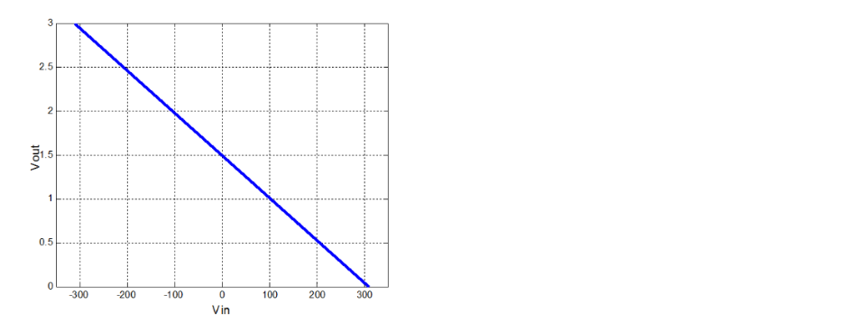
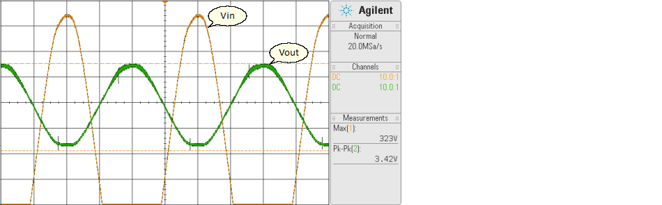
<< Click to Display Table of Contents >> Vin = AC 220 V (±311 V), Vout = 0 – 3 V |
  
|
|
<< Click to Display Table of Contents >> Vin = AC 220 V (±311 V), Vout = 0 – 3 V |
|
This situation shows an op-amp based circuit to transform a high-voltage AC waveform into something that a micro-controller can measure directly.
DISCLAIMER: This article no guarantee that the circuit will work in your situation, or that it will be safe. If you’re going to attempt to measure mains voltages, do so at your own risk . If you don’t understand the math or circuit diagram, then you probably shouldn’t be working with mains anyway. I am not responsible for your mistakes. You have been warned.
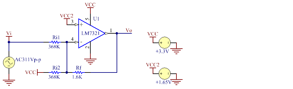
This circuit look reasonably familiar with the standard inverting amplifier. However, the key differences are that the non-inverting input is tied to half of Vcc instead of ground (so if you have a 5 V microcontroller, tie this to 2.5 V), and the extra resistor pulling the inverting input up to Vcc. The value of resistor can calculate by:
Example
Vo = (-Rf/Ri)Vi + (0.5Vcc)
and Ri1 = Ri2
Give Rf = 1.6 kΩ and Ri = 368 kΩ, Vi = -311 V, Vo = 3V
Ri = (-Rf × Vi)/(0.5Vcc-Vo)
= (-1.6kΩ × -311V)/(0.5×3.3V-3V)
= 368.59 kΩ
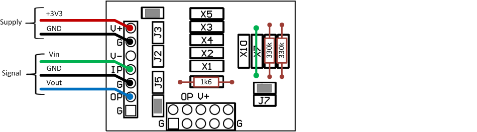
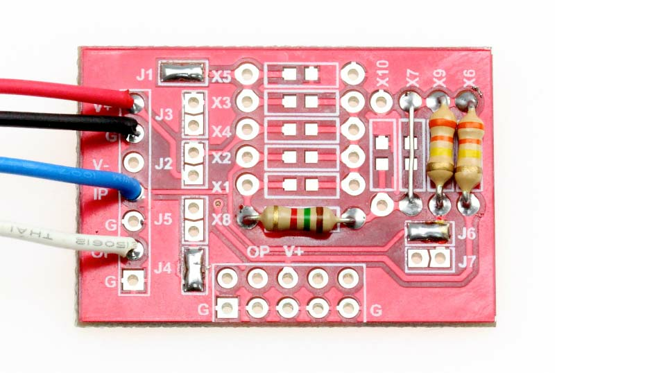
Configuration of aMG SIGCON-A: Soldering to Jump J1, J4, J6, and X7. Place Ri resistor to X6, X9 and Rf to X8.
Note Some resistor's value which we use in this trial are approximately. You should change these value or use variable R to adjust the accuracy of the output.