|
<< Click to Display Table of Contents >> Target Setup |
  
|
|
<< Click to Display Table of Contents >> Target Setup |
|
A single instance of this block must be inserted in every STM32F4 Target Simulink model. This block is used to setup the target to:
| 1. | Generate code for the selected STM32F0 target from a list of supported MCU. |
| 2. | Select and control the Cross Compiler for use to compile the generated code. See the following documents for compiler 's options: |
| a. | GNU Tools for ARM Embedded Processors contains documentation for GNU GCC compiler. |
| b. | IAR C/C++ Development Guide Compiling and linking for Advanced RISC Machines Ltd’s ARM® Cores (pdf) describes EWARM compiler & linker command line usages and options. |
| c. | ARM® IAR Assembler Reference Guide for Advanced RISC Machines Ltd’s ARM Cores (pdf) describes EWARM assemble command line usages and options. |
| 3. | Set up various system clocks for the target. |
| 4. | Control the entire Build Process from automatic compiling to download (flash programming). |
Waijung Blockset supports "Multirate Single Tasking" scheduling. This means the base interrupt timer (based on SysTick Module) will be automatically set at the smallest sample time of a system. For example, assume that you set your system to operate at 2 different rates, say, at every 0.1sec and 1sec, the generated code will be such that SysTick Interrupt Service Routine interrupts at every 0.1sec to execute the 0.1sec tasks, and, in addition, at every 10th SysTick interrupt, the 1sec tasks will also be executed automatically.
In this sense, you only need to make sure that all tasks are performed within the specified smallest sample time, e.g. in the above example 0.1sec.
You can configure the system to operate at Multirates by simply assign the required sample time in each sample time filed in each block mask parameter, under one required condition, i.e. every sample time must be a multiple of the base (smallest) sample time. You can use -1 to inherit sample time (from previous block).
Press CTRL + J to see color legend of each sample time.
See [1] for more information about Simulink generated code Task Scheduling.
Systick is a special 24-bits timer. As such, it can count up to 224-1 = 16777215 counts. Each Systick count takes 1/HCLK seconds. For instance, if you set the HCLK to the maximum of 48MHz, Systick timer can count up to 16777215/(48x106) = .3495 seconds. This is the largest possible time steps for your system; meaning, all task that are based on native Simulink blocks must be completed within this time interval. So if you set up your system to operate very slowly, for instance, if the smallest sample time (counting all blocks in the system) is 1 second, you have got a problem because Systick can count only up to 0.0999 seconds (your time step interval can not be greater than 0.0999 seconds). Waijung solves this problem by computing the greatest possible Systick value as a multiple of "1" (i.e. ..., 100, 10, 1, 0.1, 0.01, 0.001, ...) that can be used as the base sample time.
So in the above example, the base sample time of your system will be set to 0.01 sec or 10 msec automatically. Waijung select the greatest value possible, that does not violate Systick constraints, so that you have the maximum time interval possible to complete all tasks in the system.
In addition to the above mechanism, Waijung also automatically classifies tasks as real-time critical or non real-time critical (background tasks). Examples of real-time tasks are reading ADC inputs or generating DAC outputs. Examples of non real-time critical tasks are character LCD updates, CANBUS or other communication message processing, and webserver message processing. For real-time critical tasks, Waijung automatically generates and puts the core functions for such tasks in the main (Systick) timer interrupt service routines. The provision of non real-time task mechanism allows for more flexible and practical applications. For instances, a user can configure a system to operate with a fast inner-control loop (such as driving PWM or input capturing signals) as a real-time critical tasks, , while having a LCD (non real-time task) updates at 30Hz rate running without blocking the real-time critical functions. Provisions, in a form of Asynchronous Interrupt Function Call Sub-System, are made available if real-time responses are needed for uses with non-real time critical tasks.
Because Waijung tries to determine the sample times automatically for you, it is necessary to "Update the Diagram" twice. The first Update is to determine sample time of all blocks in the system, except the Target set up block. The second Update is to determine the base sample time (Target Setup Block sample time) based on information of the first Update.
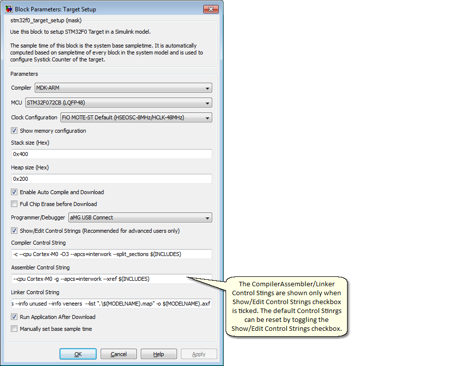
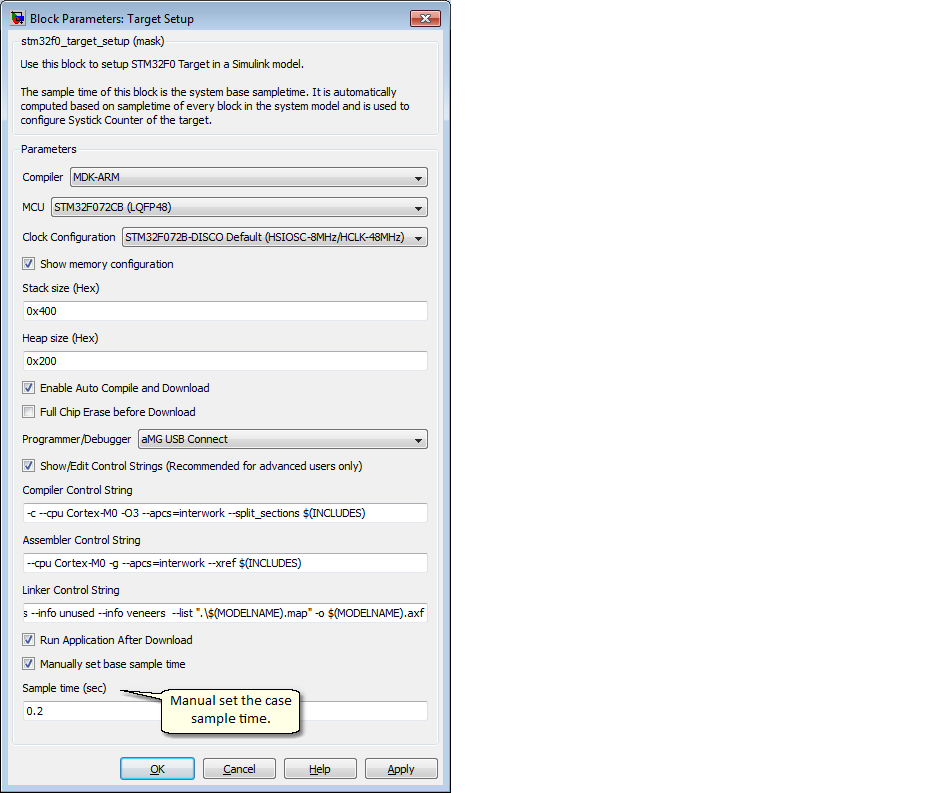
It is possible to override automatic base sample time determination by enable the "Manually set base sample time" check box as shown below.
Normally, STM32F0xx clock configuration is done via the clock configuration source file “system_stm32f0xx.c”.
STMicroelectronics has made available a very easy-to-use clock configuration tool for STM32F0xx MCU which is a Microsoft Excel file (STM32F0xx_Clock_Configuration_V1.0.1.xls) that has a simple user interface for use to generate the clock configuration file “system_stm32f0xx.c”.
STM32F0xx_Clock_Configuration_V1.0.1.xls can be downloaded from [2]. It is also made available under the directory \stm32f0_target\stm32f0\utils\STM32F0xx_AN4055. of this STM32F4 Target installation. Information about this utility is available from [3].
STM32F4 Target supports highly flexible clock configuration via the use of this STMicroelectronics Clock configuration tool for STM32F0xx controllers.
There are three clock configuration options as shown below:
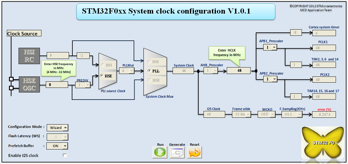
By selecting “FiO MOTE-ST Default (HSEOSC-8MHz/HCLK-48MHz)” option, STM32F4 Target will automatically use the following system_stm32f0xx.c which is generated from STM32F4xx_Clock_Configuration_V1.0.1.xls with the options as shown in Figure 1. This configuration is basically suited for use with such boards as FiO MOTE-ST which uses a 8MHz external crystal at the highest working (HCLK) clock speed of 48MHz.
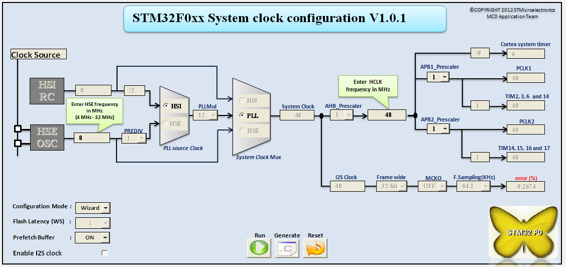
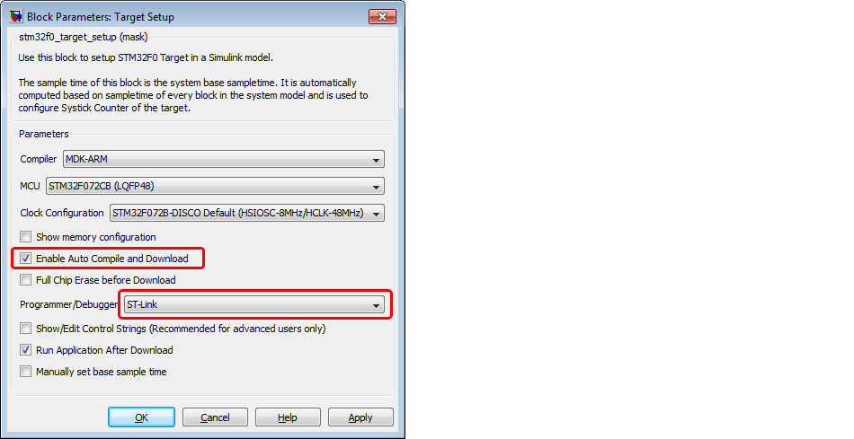
By selecting “STM32F072B-DISCO Default (HSIOSC-8MHz/HCLK-48MHz)” option, STM32F4 Target will automatically use the following system_stm32f4xx.c which is generated from STM32F0xx_Clock_Configuration_V1.0.1.xls with the options as shown in Figure 2. This configuration is basically suited for use with such boards as STM32F072B-DISCO which uses a internal 8MHz oscillator at the highest working (HCLK) clock speed of 48MHz.
By selecting “Custom (system_stm32f0xx.c)” option, STM32F4 Target will automatically use the system_stm32f0xx.c file that resides in the directory \stm32f0_target\stm32f0\utils\STM32F0xx_AN4055. Hence a user can generate any custom clock configuration (via system_stm32f0xx.c file) to configure clocks of any STM32F0xx target board with the STMicroelectronics clock configuration tool.
Below is the list of supported programmer tool for auto download:
1. ST-Link programmer
| o | Follow Software_installation for tool setup. |
| o | The programming interface is SWD. |
| o | Target setup configuration to enable ST-Link auto download |
2. aMG USB Connect
| o | Follow Software_installation for FTDI USB Driver setup. |
| o | The programming interface is UART IAP and build in Boot loader. The programmer tool is automatic control BOOT/Reset pin. |
| o | Target setup configuration to enable aMG USB Connect auto download |

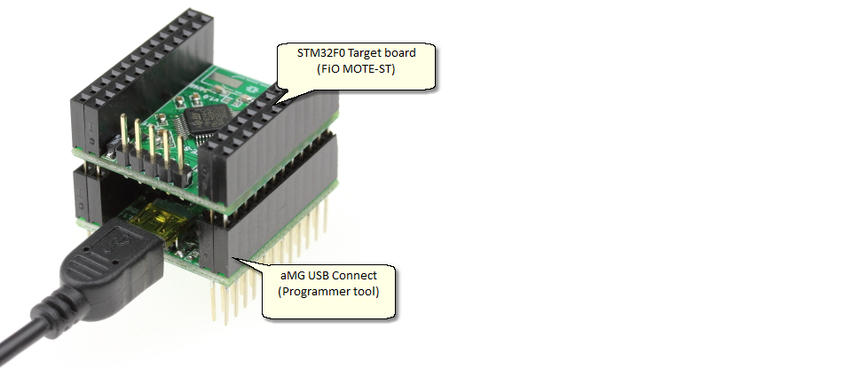
| o | Target STM32F0 board (FiO MOTE-ST) stacked on top of programmer board (aMG USB Connect). |