|
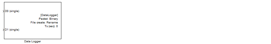
<< Click to Display Table of Contents >> Data Logger |
  
|
|
<< Click to Display Table of Contents >> Data Logger |
|
Configuration item |
Selectable option/ Value |
Description |
|---|---|---|
Variable filename |
Checked | Unchecked |
Checked: file name is input port of block. Use Volatile Data Storage Read (Type string) as file name. Unchecked: Use constant file name for data logger. |
File name |
(Specify a valid file name) |
Note: not support Unicode. |
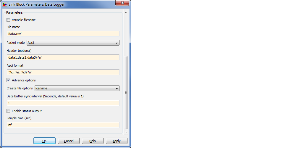
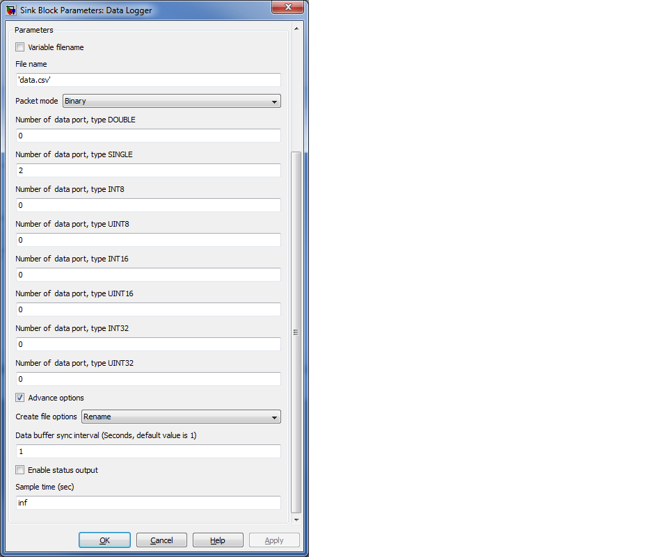
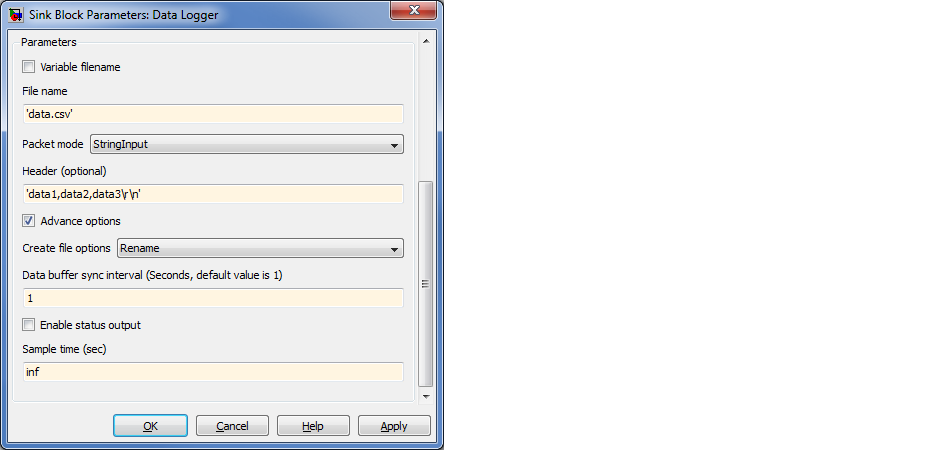
Packet mode |
Ascii | Binary | BinaryVector | StringInput |
Ascii: This mode allow user to configure the format of logging data, output is text file. Data type of input specify by sprintf format. Binary: This mode allow user specify number of data type. BinaryVector: This mode similar to Binary mode, but number of data type is data Width of vector port, suitable for storing large size of data. StringInput: This mode is allow logging data from Volatile Data Storage Read (Type string) block. Similar to %s in Ascii mode, but size is not limit. |
Header (Optional) |
(Specify header string) |
This string will be written as data header on logging start. |
Ascii format |
(Specify packet format string) |
String format support below data type: - uint32: %u, %i, %o, %x - int32: %d - single: %e, %g, %f - int8: %c - string: %s (Volatile Data Storage Read). Size of string is limit to 255. |
Number of data port, type DOUBLE |
(Port Number/ port Width of data type double) |
Binary mode: Specify number of port data type double. BinaryVector mode: Specify data width of port type double. |
Number of data port, type SINGLE |
(Port Number/ port Width of data type single) |
Binary mode: Specify number of port data type single. BinaryVector mode: Specify data width of port type single. |
Number of data port, type INT8 |
(Port Number/ port Width of data type int8) |
Binary mode: Specify number of port data type int8. BinaryVector mode: Specify data width of port type int8. |
Number of data port, type UINT8 |
(Port Number/ port Width of data type uint8) |
Binary mode: Specify number of port data type uint8. BinaryVector mode: Specify data width of port type uint8. |
Number of data port, type INT16 |
(Port Number/ port Width of data type int16) |
Binary mode: Specify number of port data type int16. BinaryVector mode: Specify data width of port type int16. |
Number of data port, type UINT16 |
(Port Number/ port Width of data type uint16) |
Binary mode: Specify number of port data type uint16. BinaryVector mode: Specify data width of port type uint16. |
Number of data port, type INT32 |
(Port Number/ port Width of data type int32) |
Binary mode: Specify number of port data type int32. BinaryVector mode: Specify data width of port type int32. |
Number of data port, type UINT32 |
(Port Number/ port Width of data type uint32) |
Binary mode: Specify number of port data type uint32. BinaryVector mode: Specify data width of port type uint32. |
Advance options |
Checked | Unchecked |
To enable or disable advance options. |
Create file options |
Append | Rename |
User can select below action for existing file on SD Card. Append: Open file and append data. Rename: Create new file name with running number. example: if data.txt is already exsting, it will create file data(1).txt instead for new logging process. Note: Maximum running number of file is 32. |
Data buffer sync interval |
(Specify time interval, default is 1) |
This mode allow user to specify interval to update file (File system internal action, to update file size to file header). This action is blocking mode and take quite long time (100 to 400ms) depend on speed of SD card. For High speed SD Card write block, this action will process in non-blocking mode (background). |
Enable status output |
Checked | Unchecked |
To enable of disable status port. This port will return 0 when Success, otherwise fail. |
Sample time (sec) |
-1 for inherited, or specify |
Specify sample time value, this will be interval time of data logger for a record. |
1. User may use Enable subsystem to start and stop data logging.
2. Remove SD Card: SD Card allow to remove during logging process, but last packets may loss. Note: Example for Data buffer synch interval configured to N seconds, the last packet in 0-N second will be loss when card removed.
3. IMPORTANT: To insert SD Card, when SD card remove and need to re-insert again, please disconnect all DC power supply to the board before insert the card.
1. The block suitable for low data rate logging, example 0.5 Second or longer per packet. For high speed data rate, use High speed SD Card write.