|
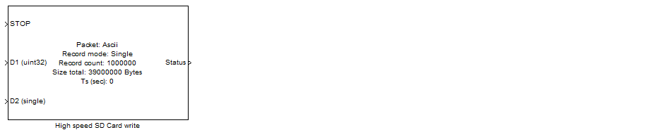
<< Click to Display Table of Contents >> High speed SD Card write |
  
|
|
<< Click to Display Table of Contents >> High speed SD Card write |
|
Configuration item |
Selectable option/ Value |
Description |
Packet mode |
Ascii | Binary |
Select mode of data format to store into SD Card. Output file of data logger in Ascii mode can be open with text viewer software, output file in Binary mode need to open with Hex viewer or custom development software. |
Record mode |
Single shot | Loop back |
Currently record mode available in Single shot only. |
Max number of logging record |
(Input a number) This number is uint32 format. |
Specify number of packet to log. |
Record size (bytes) |
- |
This is read only, showing number of bytes to store in SD card. Record size = PACKET_SIZE * RECORD_COUNT.
Note: For packet Ascii mode, Record size is only estimated number. |
Buffer size (bytes) |
32768 |
This is buffer for data record. The actual buffer size require for this data logger will be 32768*2 (double buffer). |
Card initialize option |
Format as FAT32 (Remove all existing files) | Reject if not empty |
This is for security option: When configured to "Format as FAT32", all files in SD card will erased automatically. But when configured as "Reject if not empty", card will be reject if it is not empty.
Note: SD card will re-format into FAT32 with 32k cluster size. |
Ascii format |
format of ascii record. example: %d, %f\r\n Note: %d - convert int32 to string. %u - convert uint32 to string. %f - convert single to string. %x - contert uint32 to Hex. This is available when select packet mode to Ascii |
Specify packet format. |
Number of data type DOUBLE, Number of data type SINGLE, Number of data type INT8, Number of data type UINT8, Number of data type INT16, Number of data type UINT16, Number of data type INT32, Number of data type UINT32 |
(Specify number of using data type and count) This is available when select packet mode to Binary. |
Specify data type and count for store data. |
GPIO status port |
Not used | A | B | C | D | E | F | G | H | I |
Specify port for control LED, status indicator. |
GPIO status pin, Busy |
0 | 1 | 2 | 3 | 4 | 5 | 6 | 7 | 8 | 9 | 10 | 11 | 12 | 13 | 14 | 15 |
The block will drive this pin to High to indicate Busy process. |
GPIO status pin, Progress |
0 | 1 | 2 | 3 | 4 | 5 | 6 | 7 | 8 | 9 | 10 | 11 | 12 | 13 | 14 | 15 |
The block will blink this pin 5Hz to indicate writing process, and 0.25 Hz to indicate data logger operation Stop with success. |
GPIO status pin, Error |
0 | 1 | 2 | 3 | 4 | 5 | 6 | 7 | 8 | 9 | 10 | 11 | 12 | 13 | 14 | 15 |
The block will drive this pin to High to indicate Error process. |
Sample time (sec) |
-1 for inherited, or specify |
Specify sample time value, this will be interval time of data logger for a record. |
How logging process stop:
1. Disk full (Max 32GB by design, tested with 8GB).
2. Number of logging record is equal to "Max number of logging record".
3. Manual stop, by assigning value 1 to input port 'STOP' (or use GPIO Input to get button pressed status).
1. Limit only one "High speed data logger" block in a model.
2. Reserve 250MB of SD card memory as not used due to too many timing error on first 250MB region.
3. Logger data file will spitted into multiple files if size exceed 3.99GB.
1. Card speed (example: 4MBytes/Sec, 10MBytes/Sec, or higher).
2. Buffer size (Currently 32k and will be more when use external SDRAM).
3. Sample time.
4. Record size.
1. Record size cannot exceed buffer size.
2. Record speed cannot exceed Card speed.
Given:
- Packet, to log one 32bit counter and two analog reading value in Raw format (uint16), packet size will be 8 bytes (4bytes + 2 bytes + 2bytes).
- Speed, 50 uS per sample (record).
So, logging speed will be 8byte/50uS.
8bytes/0.000050 Sec = 160000 Bytes/Sec
Given, N = Number of logging record.
So, Output size = N * Record size.
Given, N = Number of logging record.
So, Logging time (S) = sample time (S) * N
1. LED Busy, this LED will turn on at start logging process during perform Card initialization (Format, pre-allocate space for data logging). This busy period can take up to few minutes if number of logging is too large, or few minutes if number of data it small.
2. LED Progress, this LED will blink 5Hz (ON 0.1S/ OFF 0.1S) during data logger progressing. And will blink in 0.25Hz (ON 2S/ OFF 2S) if progress is finish then user can remove card.
3. LED Error, this LED will turn on when error detected during logging process.
When finish logging data, user can review MSG.TXT for information and error message. It will show timing error if sample time cannot be real-time.
Timing error may caused from Card speed and internal Card processing. Below is an example of timing error.
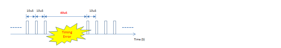
If Sampling time is set to 10uS, a sample has timing error if it take longer than 10uS.
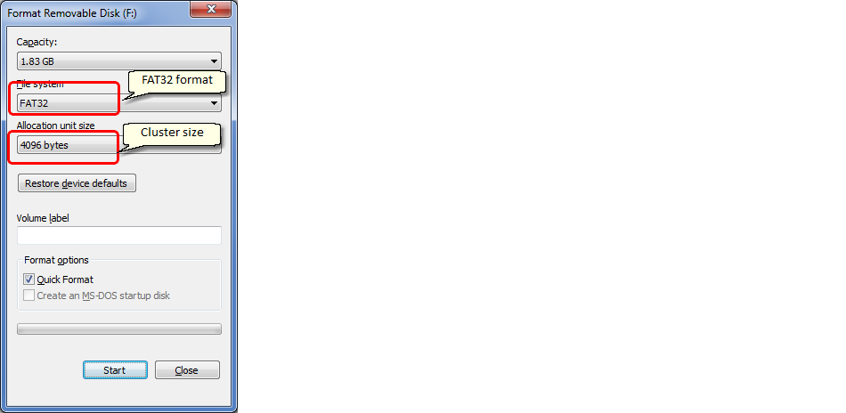
1. When data logging process start, the SD card will be re-formatted (All existing file will be loss).
2. SD Card will be automatic format to FAT system with 32kBytes cluster size, and number of FAT is 1 (no FAT backup). User can change to its default format with Windows explore. Below is recommended setting for format SD Card.
Data logger Ascii mode (10kHz)